Deep scarification rotary plow

A plowing and subsoiling technology, which is applied in the field of subsoiling rotary plowing, can solve the problems of low work efficiency, low seedling emergence rate, and inability to plow into the soil, and achieve the effect of high work efficiency, high seedling emergence rate, and soft soil

Active Publication Date: 2016-08-24
魏强
View PDF16 Cites 1 Cited by
  • Summary
  • Abstract
  • Description
  • Claims
  • Application Information

AI Technical Summary

Problems solved by technology

[0002] The patent number is ZL201010582895.6, and the Chinese invention patent with the authorized announcement number CN102084737B discloses a rotary plow. Although this rotary plow overcomes the shallow depth of the single rotary plow, it is especially suitable for the land where the straw is returned to the field. When the straw is not turned into the soil, the land is breathable, does not retain moisture, and the emergence rate is low, which further affects the yield and the plow plow cannot fully mix the fertilizer with the soil. The state arrangement affects the uniform distribution of fertilizers in the soil. The nutrients of fertilizers cannot reach the roots of all seedlings evenly, and there are plates and agglomerations. Especially when plowing the land where straw is returned to the field, the fertilizer can be raked out of the ground when raking the land, so that The disadvantage that fertilizers can’t play a role; but this kind of rotary plow has a single function, first of all, it does not have the function of deep loosening, and it also has to harrow the ground and level the soil moisture separately, and also has a special person to spread the fertilizer, so the work efficiency is low

Method used


Image

  • Deep scarification rotary plow
  • Deep scarification rotary plow
  • Deep scarification rotary plow

Examples


Embodiment Construction

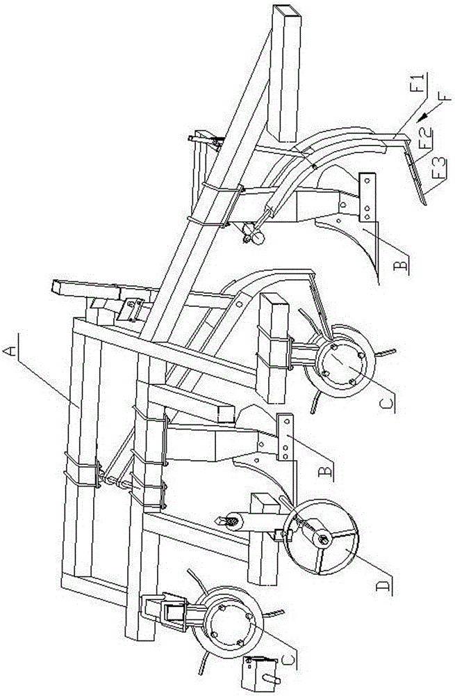
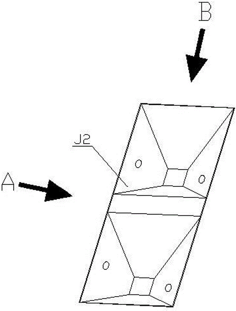
[0021] As shown in the figure, the subsoiling rotary plow is composed of a plow frame A, a plow share B and a rotary plow C. The plow share B is installed on the plow frame A. The rotary tiller is an "L"-shaped single-direction soil-throwing rotary knife, the throwing direction of the rotary plow C is the same as that of the plowshare B, and the width of the rotary plow C is the same as that of the plowshare B. , the rotary tillage depth of the rotary plow C is less than the plowing depth of the plowshare B, a gearbox E is installed on the upper part of the plow frame A, the input shaft E1 of the gearbox E is connected with the tail shaft of the tractor, and the output shaft of the gearbox E The shaft E2 is provided with a rotary tillage driving sprocket E21, and the number of the rotary tillage driving sprocket E21 is the same as that of the rotary tillage plow C, and the rotary tillage driven sprocket C11 is arranged on the shaft of the rotary tillage plow C. The tillage dri...


PUM


Abstract

A deep scarification rotary plow is composed of a plow frame, a plow share and rotary plow bodies. The plow share is installed on the plow frame. The rotary plow bodies are installed right ahead of the plow share. A rotary blade of each rotary plow body is an L-shaped single-direction soil throwing rotary blade. The soil throwing direction of the rotary plow bodies is the same as the soil turning direction of the plow share. The rotary tillage width of the rotary plow bodies is the same as the soil turning width of the plow share. The rotary tillage depth of the rotary plow bodies is smaller than the soil turning depth of the plow share. A gearbox is installed at the upper portion of the plow frame. An input shaft of the gearbox is connected with a tail shaft of a tractor. Rotary tillage driving chain wheels are arranged on an output shaft of the gearbox. The number of the rotary tillage driving chain wheels is the same as the number of the rotary plow bodies. Rotary tillage driven chain wheels are arranged on shafts of the rotary plow bodies and connected with the rotary tillage driving wheels through chains. A deep scarification shovel is arranged at the rear portion of the plow share. Compared with the prior art, the deep scarification shovel has the deep scarification function, is deep in seedling root, capable of preventing lodging and higher in yield, further has the functions of harrowing, automatic fertilizer sowing, dead furrow flattening, soil crushing and the like and is high in working efficiency.

Description

technical field [0001] The invention relates to a farming machine, in particular to a subsoiling rotary plow with a subsoiling shovel combined with a rotary plow and a plow. Background technique [0002] The patent number is ZL201010582895.6, and the Chinese invention patent with the authorized announcement number CN102084737B discloses a rotary plow. Although this rotary plow overcomes the shallow depth of the single rotary plow, it is especially suitable for the land where the straw is returned to the field. When the straw is not turned into the soil, the land is breathable, does not retain moisture, and the emergence rate is low, which further affects the yield and the plow plow cannot fully mix the fertilizer with the soil. The state arrangement affects the uniform distribution of fertilizers in the soil. The nutrients of fertilizers cannot reach the roots of all seedlings evenly, and there are plates and agglomerations. Especially when plowing the land where straw is re...

Claims


Application Information

Patent Timeline
IPC IPC(8): A01B49/02A01B49/06
CPCA01B49/025A01B49/027A01B49/065
Inventor 魏强
Owner 魏强
Why Eureka
Try Eureka