Electric power splicing fitting
A technology for connecting fittings and electric power. It is applied in the direction of conductive connection, electrical component connection, circuit, etc. It can solve problems such as easy loosening and poor firmness, and achieve the effect of ensuring stability and reliability and excellent anti-loosening effect
- Summary
- Abstract
- Description
- Claims
- Application Information
AI Technical Summary
Problems solved by technology
Method used
Image

Examples
Embodiment 1)
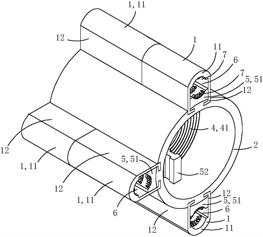
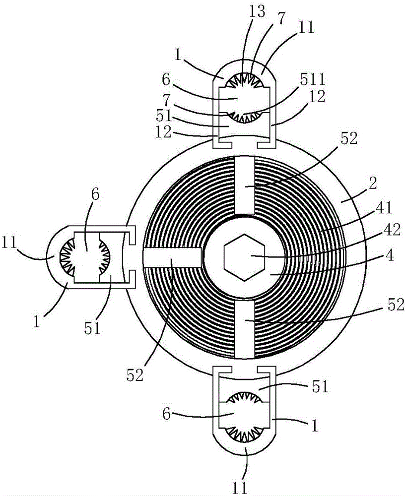
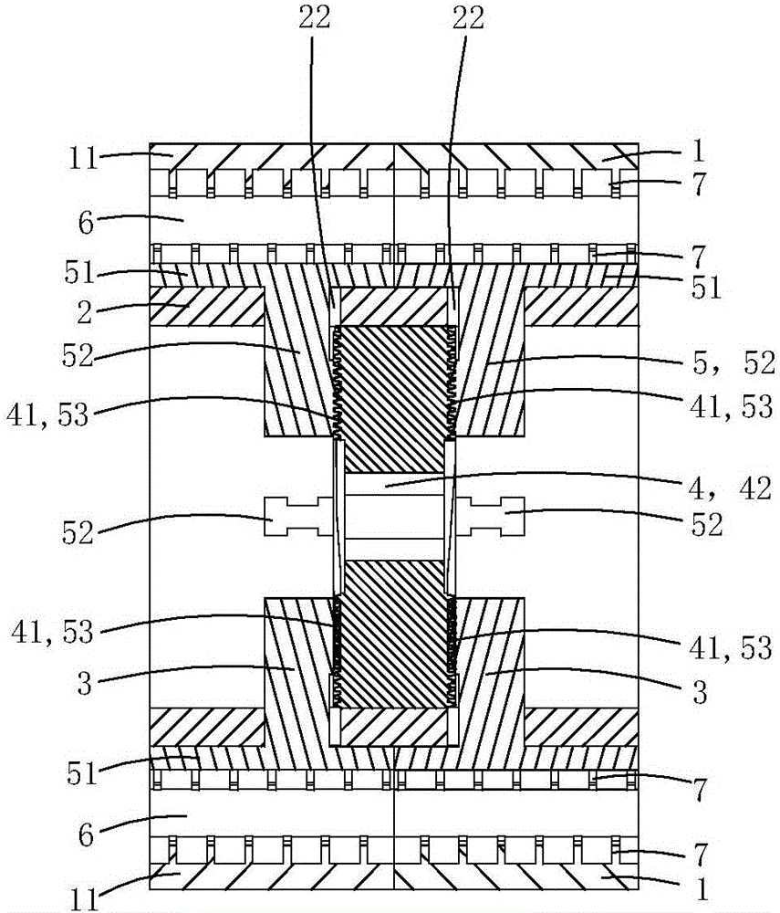
[0017] This embodiment is a kind of power connection fittings, see Figure 1 to Figure 4 As shown, it includes a core tube 2, two sets of pressing jaw assemblies 3, a flat nut 4 and two sets of crimping assemblies.
[0018] The tube wall of the core tube is provided with six radial limiting sliding holes 22, and each radial limiting sliding hole runs through the core tube tube wall along the radial direction of the core tube; each radial limiting sliding hole is located in the axial direction of the core tube. In the upper middle part, the radial cross-sectional shape of each radial limiting hole is I-shaped. In this embodiment, the six radial limiting holes are divided into two groups, and the three radial limiting holes in each group are used for matching with a corresponding set of pressing jaw assemblies.
[0019] Each set of crimping components is used to adapt to a corresponding set of pressing jaw components, and each set of crimping components includes three crimping ...
Embodiment 2)
[0034] This embodiment is basically the same as Embodiment 1, the difference is: see Figure 5 to Figure 6 As shown, at least one crimping piece 1 is provided with a mounting screw hole 15 penetrating through the pressing plate part in the radial direction of the core tube; a temperature sensing device 8 is fixed in the mounting screw hole.
[0035] The temperature sensing device 8 includes a metal housing 81 made of metal material with a containing groove 811, a temperature sensor 82 arranged in the containing groove, and a spring 83 for crimping the temperature sensor on the bottom wall of the containing groove , The screw tube plug 84 that is used for limit spring.
[0036] One end 812 of the metal shell close to the central axis of the core tube is provided with a heat conduction boss 813 used as a puncture, and one end 814 of the metal shell away from the central axis of the core tube is provided with an inner hexagonal screw groove 815; There is an external thread 816 a...
Embodiment 3)
[0044] This embodiment is basically the same as the above-mentioned embodiment 2, the difference is: see Figure 7 with Figure 8 As shown, in this embodiment, a current transformer 9 is sheathed and fixed on the outer peripheral wall of the crimping member, and the current transformer 9 includes a ring-shaped induction body 91 and an intelligent control module 92 .
[0045] The intelligent control module is provided with two electrical sockets protruding inward (not shown in the figure), and each electrical socket is inserted into a corresponding electrical socket, so that the temperature sensor and the central control circuit in the intelligent control module connected.
[0046] In this embodiment, a part of the intelligent control module is arranged in the area enclosed by the inner wall of the annular base, the outer wall of the core tube and the outer wall of the crimping piece, so as to make full use of the space and facilitate the overall compactness and integration. ...
PUM
 Abstract
Description
Claims
Application Information
 - R&D
- Intellectual Property
- Life Sciences
- Materials
- Tech Scout
- Unparalleled Data Quality
- Higher Quality Content
- 60% Fewer Hallucinations
Browse by: Latest US Patents, China's latest patents, Technical Efficacy Thesaurus, Application Domain, Technology Topic, Popular Technical Reports.
© 2025 PatSnap. All rights reserved.Legal|Privacy policy|Modern Slavery Act Transparency Statement|Sitemap|About US| Contact US: help@patsnap.com