Printing and dyeing cloth dehydrator

A dewatering machine and cloth technology, which is applied in the direction of processing textile material equipment configuration, removing liquid/gas/vapor by centrifugal force, etc., can solve the problems of reducing the dewatering efficiency of the dewatering machine, unable to recycle water and liquid, and having impurities.

Inactive Publication Date: 2016-08-17
超捷织造(深圳)有限公司
View PDF4 Cites 5 Cited by
  • Summary
  • Abstract
  • Description
  • Claims
  • Application Information

AI Technical Summary

Problems solved by technology

However, the above-mentioned structure has the following disadvantages: when the amount of water coming out of the dehydration bucket is large, the water will accumulate in the groove of the base, or even fill the groove, and the overloaded water will enter the dehydration bucket from the water outlet again. The cloth ...

Method used


Image

  • Printing and dyeing cloth dehydrator
  • Printing and dyeing cloth dehydrator
  • Printing and dyeing cloth dehydrator

Examples


Embodiment Construction

[0020] The specific implementation manners of the present invention will be further described in detail below in conjunction with the accompanying drawings and embodiments. The following examples are used to illustrate the present invention, but are not intended to limit the scope of the present invention.

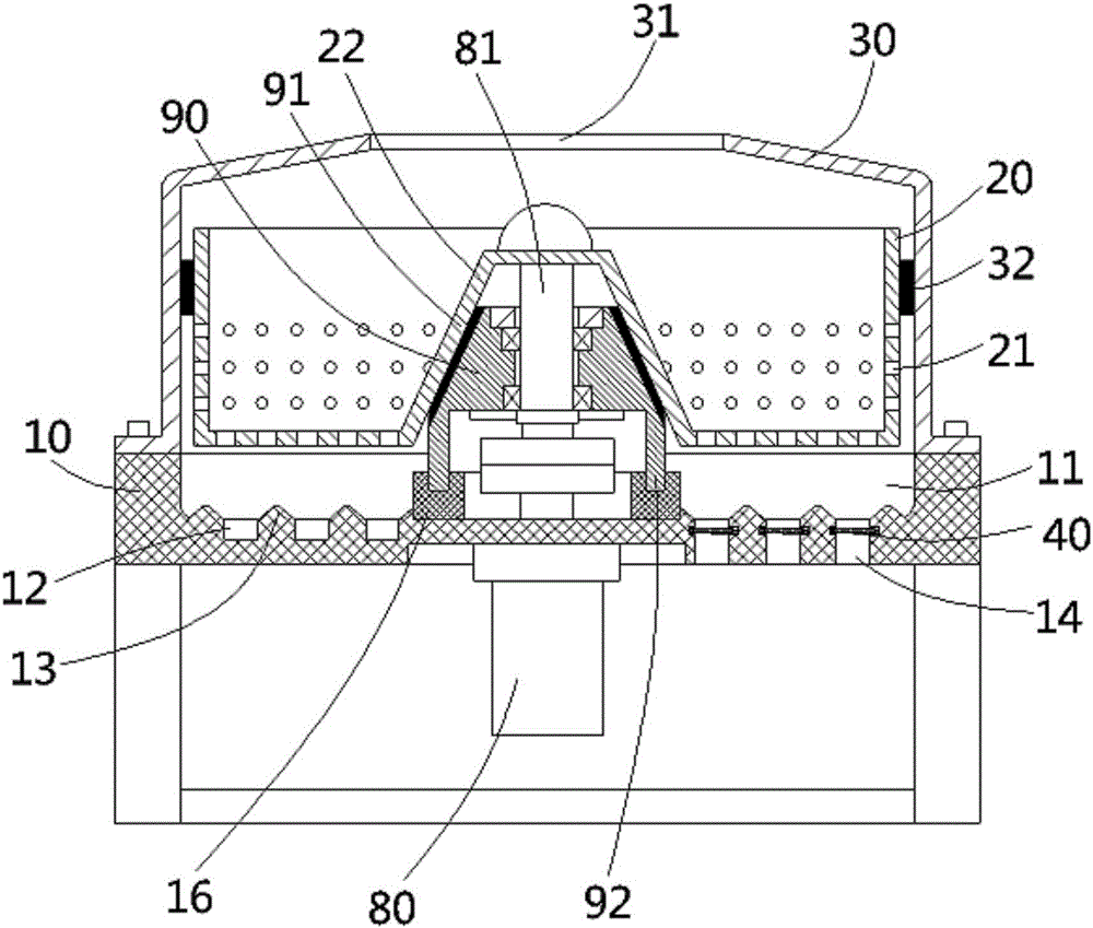
[0021] see figure 1 , a dehydrator device for printing and dyeing cloth according to the present invention, comprising a base 10, the top surface of the base has a groove 11, the groove is provided with a dehydration bucket 20, and the top surface of the base 10 is fixed There is a cylindrical protective cover 30, the top surface middle part of the cylindrical protective cover has a vertical placement through hole 31, the inner side wall of the cylindrical protective cover 30 is fixed with an annular wear ring 32, the dehydration bucket 20 is inserted into the annular wear-resistant ring 32 , the outer wall of the dehydration bucket 20 is close to the inner wall of the an...


PUM


Abstract

The invention discloses a printing and dyeing cloth dehydrator. The printing and dyeing cloth dehydrator comprises a base, a groove is formed in the top face of the base, a dehydrating barrel is arranged on the groove, multiple water outlets are formed in the dehydrating barrel, and multiple annular draining grooves are formed in the inner wall of the bottom of the groove; a drain opening is formed in the inner wall of the bottom of each annular draining groove, a pair of inserting grooves is oppositely formed in the side wall opposite to the drain openings, inserting blocks are fixedly connected to one end of a filtering net, inserting sleeves are arranged at the other end of the filtering net, and the inserting blocks and the inserting sleeves are inserted into the corresponding inserting grooves respectively; a pair of connecting rods is formed in the top face and the bottom face of the filtering net, guide grooves are formed in the connecting rods, the upper ends and the lower ends of the inserting sleeves are sleeved with the corresponding guide grooves of the connecting rods, one end of the filtering net is sleeved with the inserting sleeves, and compression springs are fixedly connected between the end of the filtering net and the inner walls of the inserting sleeves. The printing and dyeing cloth dehydrator has the advantages that water is not accumulated in the groove of the base easily, dehydrating efficiency is improved, and water obtained through dehydration can be filtered.

Description

Technical field: [0001] The invention relates to the technical field of textile machinery and equipment, in particular to a dehydrator device for printing and dyeing cloth. Background technique: [0002] The existing dehydrator for printing and dyeing fabrics throws out the moisture in the fabric, and then discharges the water through the water outlet hole on the dehydration bucket. The discharged water is temporarily buffered in the groove of the base, and then discharged through the drain on the base. Dehydrator. However, the above-mentioned structure has the following disadvantages: when the amount of water coming out of the dehydration bucket is large, the water will accumulate in the groove of the base, or even fill the groove, and the overloaded water will enter the dehydration bucket from the water outlet hole again. The cloth in the dehydration barrel is soaked again, which greatly reduces the dehydration efficiency of the dehydration machine. In addition, the drai...

Claims


Application Information

Patent Timeline
IPC IPC(8): D06B15/10D06B23/20
CPCD06B15/10D06B23/20
Inventor 吴国强
Owner 超捷织造(深圳)有限公司
Why Eureka
Try Eureka