
Complex-velocity-distribution regional rock micro-seismic seismic source positioning method

A technology of velocity distribution and seismic source location, applied in the field of geotechnical engineering, can solve problems such as large errors, limited accuracy of seismic source location, and complex distribution of rock mass wave velocities

Active Publication Date: 2016-08-10
SICHUAN UNIV
View PDF5 Cites 21 Cited by
  • Summary
  • Abstract
  • Description
  • Claims
  • Application Information

AI Technical Summary

Problems solved by technology

However, in many practical projects, especially in regional rock masses with complex velocity distributions, the regional rock mass wave velocity values ​​monitored by microseismic monitoring are not the same everywhere, and the distribution of rock mass wave velocity conditions is complex, coupled with the influence of geological structures and artificial excavation, regional The rock mass is more characterized by layered or massive velocity zoning, and in large-scale underground engineering, there is still a certain volume of cavity area
If the existing nonlinear positioning method is used to locate the microseismic source of this kind of regional rock mass with complex velocity distribution on the basis of a single velocity model, large errors will be generated, and the accuracy of source location will inevitably be limited.

Method used


Image

  • Complex-velocity-distribution regional rock micro-seismic seismic source positioning method
  • Complex-velocity-distribution regional rock micro-seismic seismic source positioning method
  • Complex-velocity-distribution regional rock micro-seismic seismic source positioning method

Examples


Embodiment

[0039] In this embodiment, the method of the present invention is used to locate the microseismic source of a certain slope project with complex velocity distribution, and the steps are as follows:

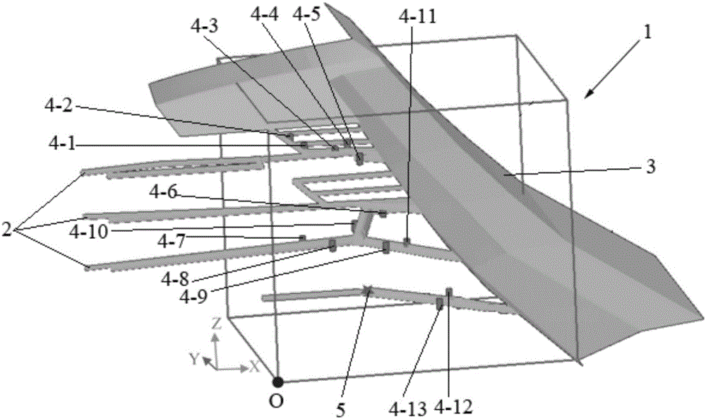
[0040] ① According to the actual monitoring requirements, delineate the monitoring area 1 to be used for microseismic source location from the slope engineering with complex velocity distribution. The monitoring area includes the corridor 2 and the slope surface 3, such as figure 1 As shown, the monitoring area is in the shape of a cuboid, with length A=300 meters, width B=300 meters, and height C=264 meters. The length direction of the monitoring area is the X direction, the width direction is the Y direction, and the height direction is the Z direction , establish a three-dimensional Cartesian coordinate system in the monitoring area, and the spatial coordinates of the corner point O of the monitoring area are (588958.4, 3012682.3, 570.0).

[0041] The monitoring area is divided...


PUM

PropertyMeasurementUnit
Lengthaaaaaaaaaa

Abstract

The invention provides a complex-velocity-distribution regional rock micro-seismic seismic source positioning method. The method comprises the following steps: 1) defining a monitor region, establishing a three-dimensional rectangular coordinate system in the monitor region and dividing the monitor region into a three-dimensional mesh, and numbering each node of the three-dimensional mesh and recording space coordinate of each node; 2) arranging sensors in the monitor region, and grouping the each sensor to the three-dimensional mesh node closest to the sensor; 3) when the monitor region has microearthquake, using the sensors to collect waveform initial arriving moment of P wave generated in the microearthquake; 4) giving corresponding wave velocity values to the nodes of the three-dimensional mesh, and with each sensor being a start point, calculating first arrival traveltime between the node where each sensor locates and the node, of which the serial number is (l, m, n) through a second-order multiple-template fast marching method; and 5) establishing and solving a time difference function f(l, m, n) corresponding to each node, and ordering the obtained function values of the f(l, m, n) in a sequence from small to large, and carrying out arithmetic average based on the node coordinates of the nodes corresponding to the front k function values of the f(l, m, n) to obtain a seismic source coordinate.

Description

technical field [0001] The invention belongs to the field of geotechnical engineering, and relates to a local rock mass microseismic source location method with complex velocity distribution, in particular to a regional rock mass microseismic source location method based on a second-order multi-template fast travel method. Background technique [0002] The microseismic monitoring technology collects the rock mass micro-fracture signals through sensors arranged in the regional rock mass, and then analyzes and delineates the rock mass damage area, which provides an effective basis for the regional rock mass stability evaluation. At present, microseismic monitoring technology has been widely used in mining, oil exploration, water conservancy and hydropower and other fields. [0003] Fast and accurate microseismic source location method is the basis for microseismic monitoring technology to effectively play the role of prediction and early warning. The location of the microseis...

Claims


Application Information

Patent Timeline
IPC IPC(8): G01V1/30
CPCG01V1/30G01V2210/65
Inventor 徐奴文郭亮戴峰赵涛李韬姜鹏
Owner SICHUAN UNIV
Learn More