
Optical fiber Fabry-Perot electric field sensor for electrostatic field measurement

An electric field sensor and electrostatic field technology, applied in the field of sensors, can solve problems such as electric field distortion and affecting test results, and achieve the effect of improving dynamic range and accuracy

Inactive Publication Date: 2016-08-10
HARBIN UNIV OF SCI & TECH
View PDF4 Cites 4 Cited by
  • Summary
  • Abstract
  • Description
  • Claims
  • Application Information

AI Technical Summary

Problems solved by technology

[0004] The purpose of the present invention is to solve the problem that the metal probe of the existing electric field sensor is easy to cause electric field distortion, thereby affecting the test results, and provides an optical fiber Fabry-Perot electric field sensor for electrostatic field measurement

Method used


Image

  • Optical fiber Fabry-Perot electric field sensor for electrostatic field measurement
  • Optical fiber Fabry-Perot electric field sensor for electrostatic field measurement
  • Optical fiber Fabry-Perot electric field sensor for electrostatic field measurement

Examples


specific Embodiment approach 1

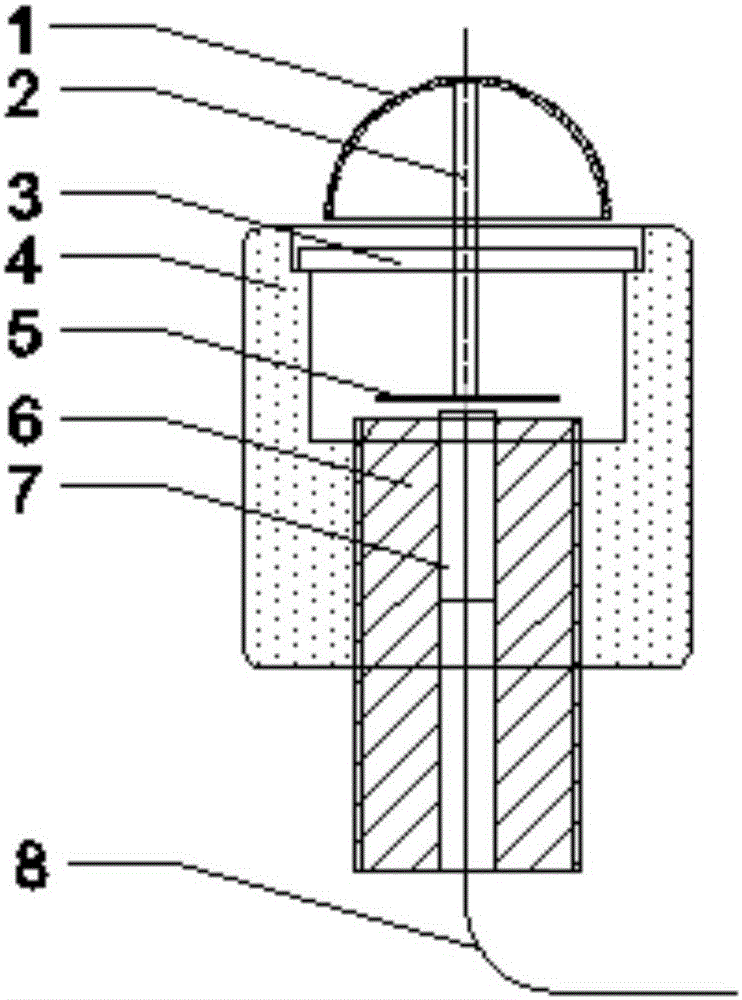
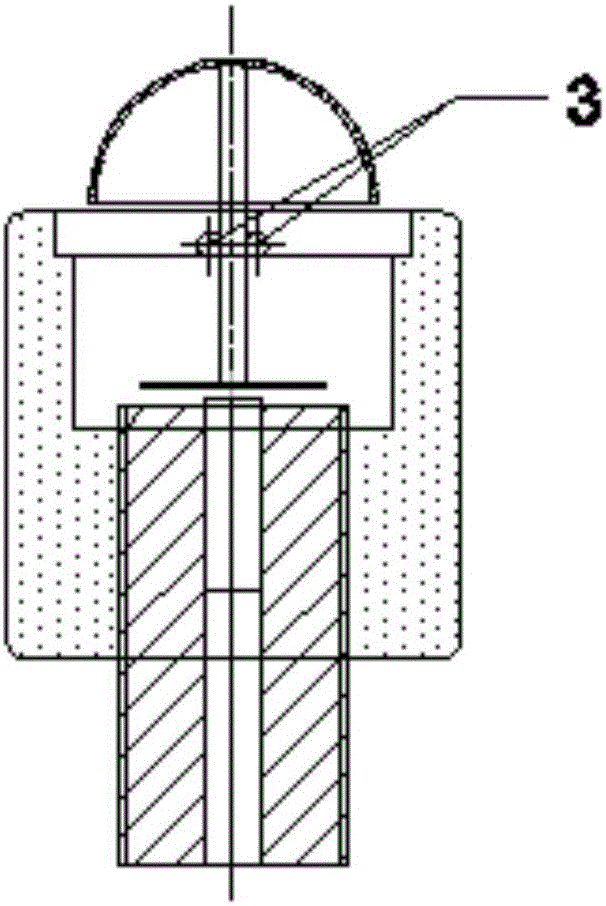
[0014] Specific implementation mode one: the following combination figure 1 with figure 2 Describe this embodiment, the optical fiber Fabry-Perot electric field sensor for electrostatic field measurement described in this embodiment, the electric field sensor includes a hollow hemisphere 1, a quartz column 2, two quartz rods 3, an insulating outer wall 4, and a quartz sheet 5 , trimmer 6 and fiber collimator 7;

[0015] Two quartz rods 3 are placed horizontally and parallel to each other. Two quartz rods 3 are welded vertically in the middle of the quartz column 2. The upper end of the quartz column 2 is glued with the hollow hemisphere 1, and the upper end of the quartz column 2 is located in the cavity of the hollow hemisphere 1. Inside, the lower end of the quartz column 2 is glued with a quartz thin slice 5, and the quartz thin slice 5 is placed horizontally. An insulating outer wall 4 is provided on the outside of the upper half of the quartz rod 3, the quartz sheet 5 ...

specific Embodiment approach 2

[0018] Embodiment 2: In this embodiment, Embodiment 1 is further explained. The hollow hemisphere 1 is made of polypropylene material, and its outer radius is 12.7 mm, and its inner radius is 11.5 mm.

specific Embodiment approach 3

[0019] Embodiment 3: In this embodiment, Embodiment 1 is further described. The radius of the section of the quartz column 2 is 1.05 mm, and the length is 30 mm.


PUM

PropertyMeasurementUnit
Outer radiusaaaaaaaaaa
Inner radiusaaaaaaaaaa
Radiusaaaaaaaaaa

Abstract

An optical fiber Fabry-Perot electric field sensor used for electrostatic field measurement belongs to the field of sensors. The invention aims to solve the problem that the metal probe of the existing electric field sensor easily causes electric field distortion, thereby affecting the test result. It includes a hollow hemisphere, a quartz column, two quartz rods, an insulating outer wall, a quartz sheet, a trimmer and an optical fiber collimator; the two quartz rods are placed horizontally and parallel, and two quartz rods are welded vertically in the middle of the quartz column, and the upper end of the quartz column The glue is inherently hollow hemisphere, and the upper end of the quartz column is located in the cavity of the hollow hemisphere, the lower end of the quartz column is inherently a quartz sheet, the quartz sheet is placed horizontally, the upper end surface of the fiber collimator is parallel to the end surface of the quartz sheet, and the fiber collimator is glued in the fine-tuning In the device, the outer sides of the two quartz rods, the quartz sheet and the upper part of the trimmer are provided with an insulating outer wall; the upper end face of the fiber collimator and the end face of the quartz sheet are coated with a film with a reflectivity of 50%, and a FP is formed between the two reflective films. cavity. The invention is used for electric field measurement.

Description

technical field [0001] The invention belongs to the field of sensors. Background technique [0002] Electric field measurement technology is not only widely used to measure the electric field intensity near high-voltage transmission lines and substations, but also provides technical means for researchers to understand and measure the electric field distribution near high-voltage equipment such as degraded insulators, transformer windings, high-voltage cable terminals, and high-voltage switches. By actually measuring the size of the electric field near the transmission line, around the substation and inside the power equipment, it provides powerful data for the research of transmission line operation status monitoring, power equipment insulation status evaluation, power equipment design and manufacturing process optimization, and power system electromagnetic compatibility. Support is of great significance to the healthy and stable operation of the entire power industry. [0...

Claims


Application Information

Patent Timeline
IPC IPC(8): G01R29/12
CPCG01R29/12
Inventor 赵洪张国帅张开玉
Owner HARBIN UNIV OF SCI & TECH
Learn More