Eureka AIR delivers breakthrough ideas for toughest innovation challenges, trusted by R&D personnel around the world.

An acoustic emission test device with an acoustic emission sensor built in a true triaxial chamber

A technology of acoustic emission sensor and test device, which is applied in the direction of material analysis, instrument, analysis material, etc. using acoustic emission technology, can solve the problem that acoustic emission signal equipment has not been reported, the number and energy of acoustic emission events are reduced, signal signal noise problems such as low ratio, to achieve the effect of achieving authenticity and reliability, improving service life, and ensuring authenticity and reliability

Active Publication Date: 2018-08-07
CENT SOUTH UNIV
View PDF4 Cites 1 Cited by
  • Summary
  • Abstract
  • Description
  • Claims
  • Application Information

AI Technical Summary

Problems solved by technology

In this case, the rock sample holder (hydraulic oil and cylinder wall in conventional triaxial) will cause the propagation distance to increase, which will cause the number and energy of the received AE event to decrease (for conventional triaxial equipment, its shear pulse The wave is because the transmission path conversion occurs because it cannot directly pass through the hydraulic oil in the three-axis chamber of the servo machine)
In addition, due to the influence of laboratory environmental noise, etc., when the acoustic emission sensor is placed on the outer wall of the triaxial, it will also be affected by many noises, especially the interference of electromagnetic signals, so the signal-to-noise ratio of the received signal is relatively low
At present, there is still no report on the research on the monitoring of acoustic emission signals in the true triaxial room and the development of related equipment.

Method used


Image

  • An acoustic emission test device with an acoustic emission sensor built in a true triaxial chamber
  • An acoustic emission test device with an acoustic emission sensor built in a true triaxial chamber
  • An acoustic emission test device with an acoustic emission sensor built in a true triaxial chamber

Examples


Embodiment Construction

[0029] Implementation of the present invention will be further described below in conjunction with accompanying drawing:

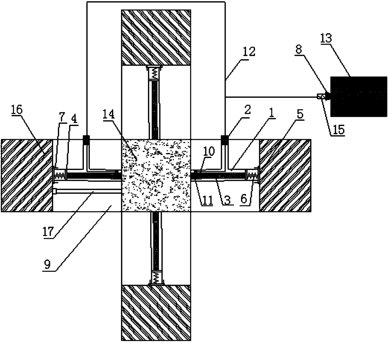
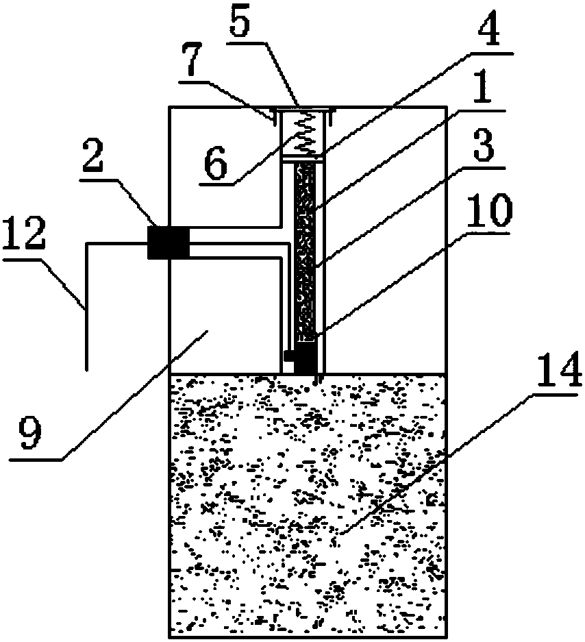
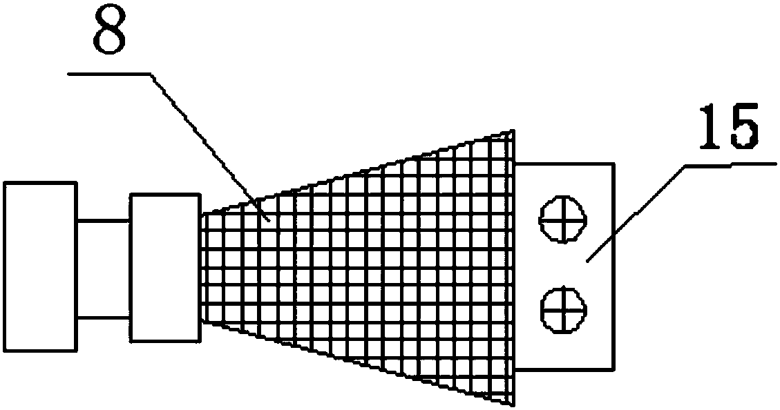
[0030] Depend on figure 1It can be seen that the device is mainly composed of a T-shaped cavity 1, a rubber plug 2, a push rod 3, a first spring washer 4, a second spring washer 5, a hard spring 6, a micro screw 7, a BNC adapter 8, a rock test Sample clamp 9, magnet sheet 10, acoustic emission sensor 11, acoustic emission signal line 12, acoustic emission preamplifier 13, rock sample 14, terminal 15, oil cylinder 16 and disturbance rod 17 components. An acoustic emission test device in which an acoustic emission sensor is built into a true triaxial chamber is realized on a true triaxial electro-hydraulic servo mutagenesis test system (TRW-3000 type). The rock sample 14 and the rock sample fixture 9 are collectively regarded as a true triaxial pressure chamber. First of all, the size and shape of the six rock sample fixtures 9 are all the same, and they a...


PUM

PropertyMeasurementUnit
diameteraaaaaaaaaa
diameteraaaaaaaaaa

Abstract

The invention discloses an acoustic emission testing apparatus with acoustic emission sensors built in a true triaxial chamber. T-shaped cavities are processed in rock sample clamps in three directions of a true triaxial electro-hydraulic servo mutagenesis testing system; the acoustic emission sensors are placed in the T-shaped cavities; a rubber plug located at an end part is used for fixing an acoustic emission signal line; the lead-out signal line is connected with a BNC adapter equipped with a terminal; the BNC adapter is directly connected with an amplifier to form a complete acoustic emission monitoring system; and the tail part of each acoustic emission sensor is fixedly connected with a push rod through a magnet piece, the push rod, a spring pad, a hard spring and minisized screws form a force-transferring mechanism together, and the acoustic emission sensor and a rock sample are allowed to always maintain tight contact in virtue of the mechanism. The acoustic emission testing apparatus is simple in structure and strong in operability; the acoustic emission sensors are repeatedly usable; considerable interference signals produced by external arrangement of the acoustic emission sensors are substantially reduced; and authenticity and reliability of acquired acoustic emission signals are guaranteed.

Description

technical field [0001] The invention relates to an acoustic emission test device based on triaxial loading and unloading, in particular to an acoustic emission test device in which an acoustic emission sensor is built in a true triaxial chamber. Background technique [0002] Deep rocks are in a three-dimensional high-stress state, and the methods for studying the mechanical properties of rocks under multi-dimensional stress state mainly include conventional triaxial experiments (σ 1 >σ 2 = σ 3 ≠0) and true triaxial experiments (σ 1 >σ 2 >σ 3 ≠0). Conventional triaxial experiments ignore the influence of intermediate principal stress on rock mechanical properties, which is not conducive to understanding the rock fracture mechanism under real stress state. To carry out the research on the mechanical properties of rock in three-dimensional stress state, it is necessary to use the true triaxial experimental system. [0003] When the rock material is subjected to ...

Claims


Application Information

Patent Timeline
Patent Type & Authority Patents(China)
IPC IPC(8): G01N29/14
CPCG01N29/14G01N2291/0232G01N2291/0289
Inventor 李地元李夕兵冯帆杜坤王少峰邱加冬
Owner CENT SOUTH UNIV
Why Eureka
Eureka Blog
Learn More