Heat exchange ventilating fan

A ventilation fan and fresh air technology, applied in the field of construction, can solve the problems of affecting temperature, thieves enter the room to steal, waste energy, etc., and achieve the effect of ensuring ventilation, cleaning, and physical and mental health

Active Publication Date: 2016-08-10
SHANDONG EOSS WINDOWS & DOOR SYST TECH CO LTD +1
View PDF9 Cites 0 Cited by
  • Summary
  • Abstract
  • Description
  • Claims
  • Application Information

AI Technical Summary

Problems solved by technology

[0003] 1. Outdoor dust is easy to enter the building through the open opening fan, polluting the air environment in the building, especially in sand, rain and snow, and spring weather, etc. Outdoor dust, rain and snow And external dirt such as floating catkins can easily enter the room and pollute the indoor air environment. If the fan is closed, the indoor ventilation effect will be poor, and the indoor air environment will not be ventilated in time, which will affect the physical and mental health of people indoors. ;
[0004] 2. When the existing opening fan is opened for ventilation, the indoor and outdoor air are in direct contact with each other for ventilation, so that the indoor air can quickly dissipate heat or cold to the outside through convection, conduction, and radiation. It is beneficial to keep the building cool in summer and keep warm in winter, which seriously affects the temperature in the building and reduces the comfort of people in the building. At this time, more energy will be wasted in order to maintain a constant temperature in the room;
[0005] 3. When the existing opening fan is opened and in the ventilation state, it is easy for thieves to enter the room to steal, which is a big loophole in the anti-theft aspect, which is not conducive to anti-theft. In addition, opening the windows of high-rise buildings also has a great potential safety hazard

Method used


Image

  • Heat exchange ventilating fan
  • Heat exchange ventilating fan
  • Heat exchange ventilating fan

Examples


Embodiment Construction

[0041] In order to make the object, technical solution and advantages of the present invention clearer, the present invention will be further described in detail below in conjunction with the accompanying drawings and embodiments. It should be understood that the specific embodiments described here are only used to explain the present invention, not to limit the present invention.

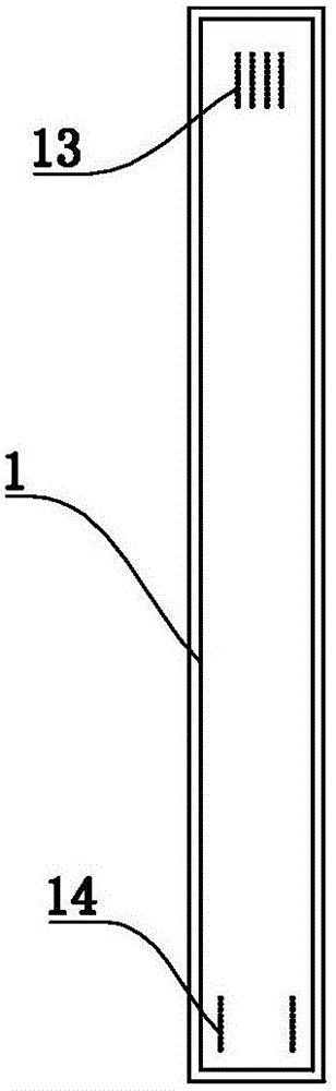
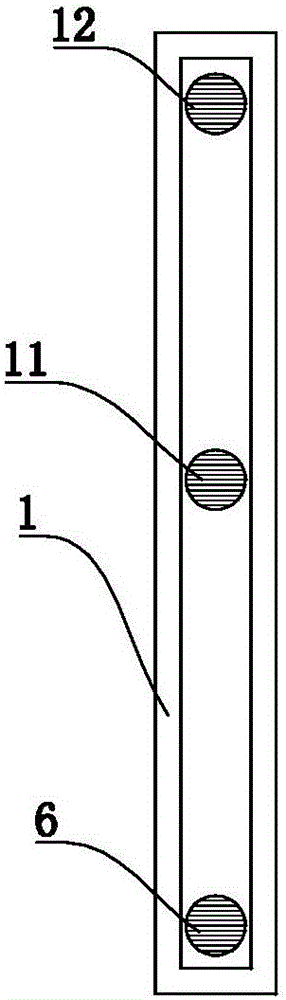
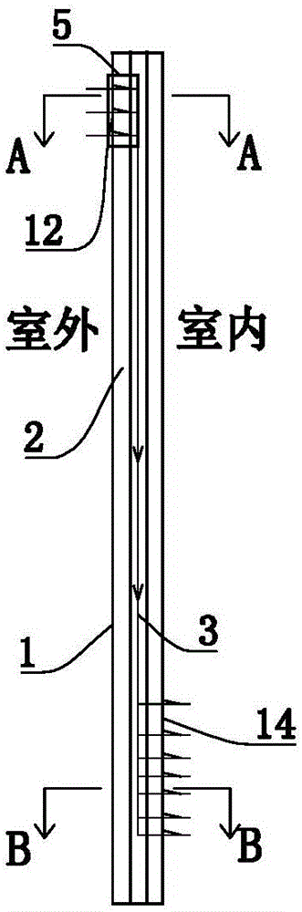
[0042] refer to figure 1 , figure 2 , image 3 , Figure 4 , Figure 5 , Figure 6 , Figure 7 , Figure 8 as well as Figure 9 , the heat exchange ventilation fan of the present invention comprises multiple partition walls 1, the multichannel partition walls 1 are arranged side by side from one side to the other side of the heat exchange ventilation fan, and every two adjacent partition walls 1 enclose a sealed The chamber 2 is used as the air outlet chamber or the air inlet chamber. Several air outlet chambers and several air inlet chambers are formed between the multiple partition walls...


PUM


Abstract

The invention discloses a heat exchange ventilating fan. The heat exchange ventilating fan comprises multiple isolating walls. The isolating walls are arranged in parallel from one side of the heat exchange ventilating fan to the other side of the heat exchange ventilating fan. A sealing cavity is defined by every two adjacent isolating walls to serve as an air outflow cavity or an air inflow cavity. Multiple air outflow cavities and multiple air inflow cavities are formed among the isolating walls and arranged at intervals. The air outflow cavities communicate with one another to form an air outflow channel allowing indoor air to be discharged out of a room. The air inflow cavities communicate with one another to form a fresh air inflow channel allowing outdoor air to enter the room. The isolating wall on the outermost side and the isolating wall on the innermost side of the heat exchange ventilating fan are each provided with air outflow holes allowing the indoor air to be discharged out of the room and fresh air inflow holes allowing outdoor air to enter the room. The air outflow holes communicate with the air outflow channel, and the fresh air inflow holes communicate with the fresh air inflow channel. By the adoption of the heat exchange ventilating fan, heat or cold energy in the building room can be stored effectively in the ventilation state, and energy saving is facilitated.

Description

technical field [0001] The invention relates to the technical field of buildings, in particular to a heat exchange ventilation fan. Background technique [0002] In order to ensure the health of people working and living in the building, the building is required to have a good ventilation effect, and the existing buildings generally realize the ventilation effect by setting opening fans on the windows. For existing traditional windows, the opening fan must be opened when ventilation is realized, so as to realize ventilation inside and outside the building. There are following defects in this ventilation mode: [0003] 1. Outdoor dust is easy to enter the building through the open opening fan, polluting the air environment in the building, especially in sand, rain and snow, and spring weather, etc. Outdoor dust, rain and snow And external dirt such as floating catkins can easily enter the room and pollute the indoor air environment. If the fan is closed, the indoor ventilat...

Claims


Application Information

Patent Timeline
Patent Type & Authority Applications(China)
IPC IPC(8): F24F7/013F24F12/00
CPCF24F7/013F24F12/006
Inventor 潘清溪
Owner SHANDONG EOSS WINDOWS & DOOR SYST TECH CO LTD
Why Eureka
Try Eureka