Locking mechanism for connecting intelligent drilling tool and pushing wing

A locking mechanism and drilling tool technology, applied in the direction of drilling equipment, drill pipe, drill pipe, etc., can solve the problems of pin falling off, impact, frequent vibration, etc., achieve the effects of preventing falling off, improving safety, and broad application prospects

Active Publication Date: 2016-08-10
BC P INC CHINA NAT PETROLEUM CORP +1
View PDF9 Cites 2 Cited by
  • Summary
  • Abstract
  • Description
  • Claims
  • Application Information

AI Technical Summary

Problems solved by technology

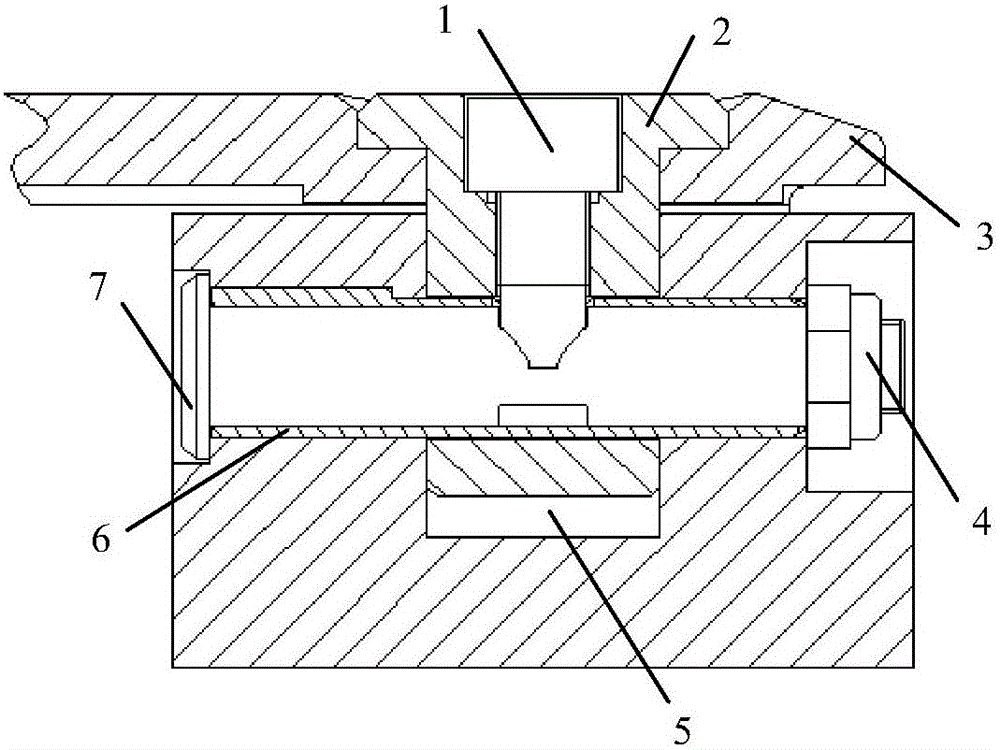
[0003] Due to the complex well conditions, frequent shocks and vibrations, and the frequent work of the pusher wing during drilling, the pins connecting the pusher wing and the tool may fall off. Therefore, in order to improve the safety and reliability of the intelligent drilling tool, a A locking mechanism for connecting the push wing and the tool

Method used


Image

  • Locking mechanism for connecting intelligent drilling tool and pushing wing
  • Locking mechanism for connecting intelligent drilling tool and pushing wing
  • Locking mechanism for connecting intelligent drilling tool and pushing wing

Examples


Embodiment Construction

[0026] It should be noted that, in the case of no conflict, the embodiments of the present invention and the features in the embodiments can be combined with each other.

[0027] In describing the present invention, it should be understood that the terms "center", "longitudinal", "transverse", "upper", "lower", "front", "rear", "left", "right", " The orientations or positional relationships indicated by "vertical", "horizontal", "top", "bottom", "inner" and "outer" are based on the orientations or positional relationships shown in the drawings, and are only for the convenience of describing the present invention and Simplified descriptions, rather than indicating or implying that the device or element referred to must have a particular orientation, be constructed and operate in a particular orientation, and thus should not be construed as limiting the invention. In addition, the terms "first", "second", etc. are used for descriptive purposes only, and should not be understood ...


PUM

PropertyMeasurementUnit
Thicknessaaaaaaaaaa

Abstract

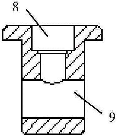
The invention provides a locking mechanism for connecting an intelligent drilling tool and a pushing wing. The locking mechanism comprises a square pin and a pin shaft. The square pin perpendicularly penetrates through the pushing wing and is connected with a tool body, the pin shaft penetrates through the tool body and the square pin and is fixed to the tool body through a locking component arranged at the tail end of the pin shaft, and an abrasion resistant sleeve is arranged between the pin shaft and the tool body. The locking mechanism for connecting the intelligent drilling tool and the pushing wing can ensure that the pin shaft does not generate axial movement under the situation that a lock nut fails, the pin shaft can be prevented from disengaging, the use safety of the intelligent drilling tool is improved, and wide application prospects are achieved.

Description

technical field [0001] The invention belongs to the field of oil drilling, and in particular relates to a locking mechanism for connecting an intelligent drilling tool with a push wing. Background technique [0002] The working mode of the intelligent drilling tool is mainly to rely on the fixed-point expansion and contraction of the pushing wing (also called the guide block) to make it contact with the well wall, and use the reaction force of the well wall to generate a lateral thrust on the drill bit to achieve guidance. The power to extend the thrusting wing comes from the hydraulic pressure of the drilling fluid, that is, the internal and external pressure difference acting on the piston. The stretching force is equal to the differential pressure (or bit pressure drop) times the area of ​​the piston. [0003] Due to the complex well conditions, frequent shocks and vibrations, and the frequent work of the pusher wing during drilling, the pins connecting the pusher wing a...

Claims


Application Information

Patent Timeline
IPC IPC(8): E21B17/12
CPCE21B17/12
Inventor 白大鹏黄峰李绍辉魏春明李志广张猛
Owner BC P INC CHINA NAT PETROLEUM CORP
Why Eureka
Try Eureka