Eureka AIR delivers breakthrough ideas for toughest innovation challenges, trusted by R&D personnel around the world.

Imaging device and imaging method

A camera device and camera technology, applied in the camera field, can solve the problems of reducing user experience, not being able to take pictures, increasing user operation time, etc.

Active Publication Date: 2016-08-03
VIVO MOBILE COMM CO LTD
View PDF4 Cites 14 Cited by
  • Summary
  • Abstract
  • Description
  • Claims
  • Application Information

AI Technical Summary

Problems solved by technology

However, in the above-mentioned auto-focusing process, the detection of the object distance by the camera device is not accurate, so a relatively fine picture cannot be captured, which not only increases the operation time of the user, but also reduces the user experience.

Method used


Image

  • Imaging device and imaging method
  • Imaging device and imaging method
  • Imaging device and imaging method

Examples


Embodiment 1

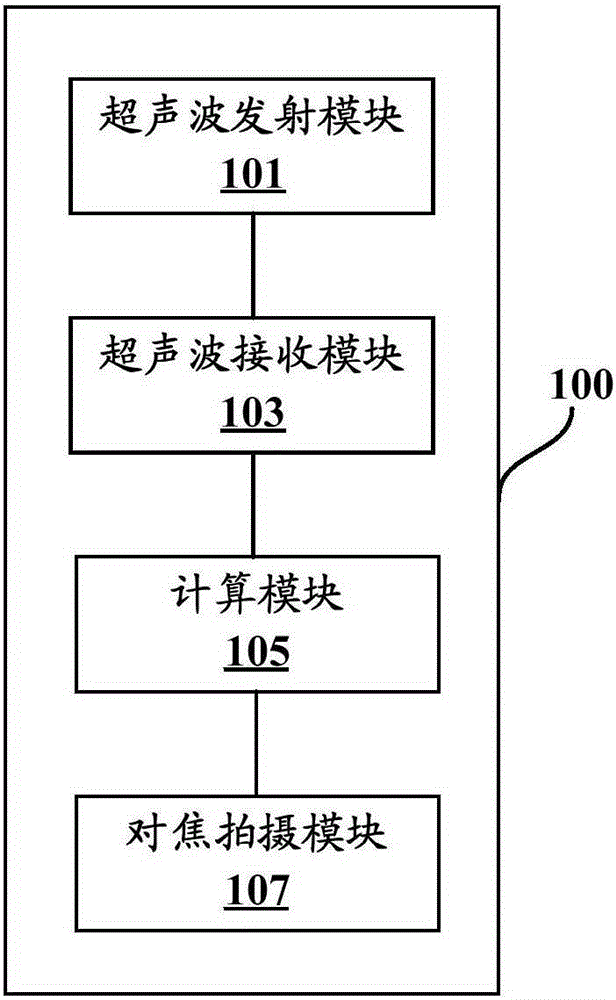
[0029] According to one aspect of the present invention, a camera device is provided, the camera device includes a camera, further, as figure 1 As shown, the camera 100 also includes:

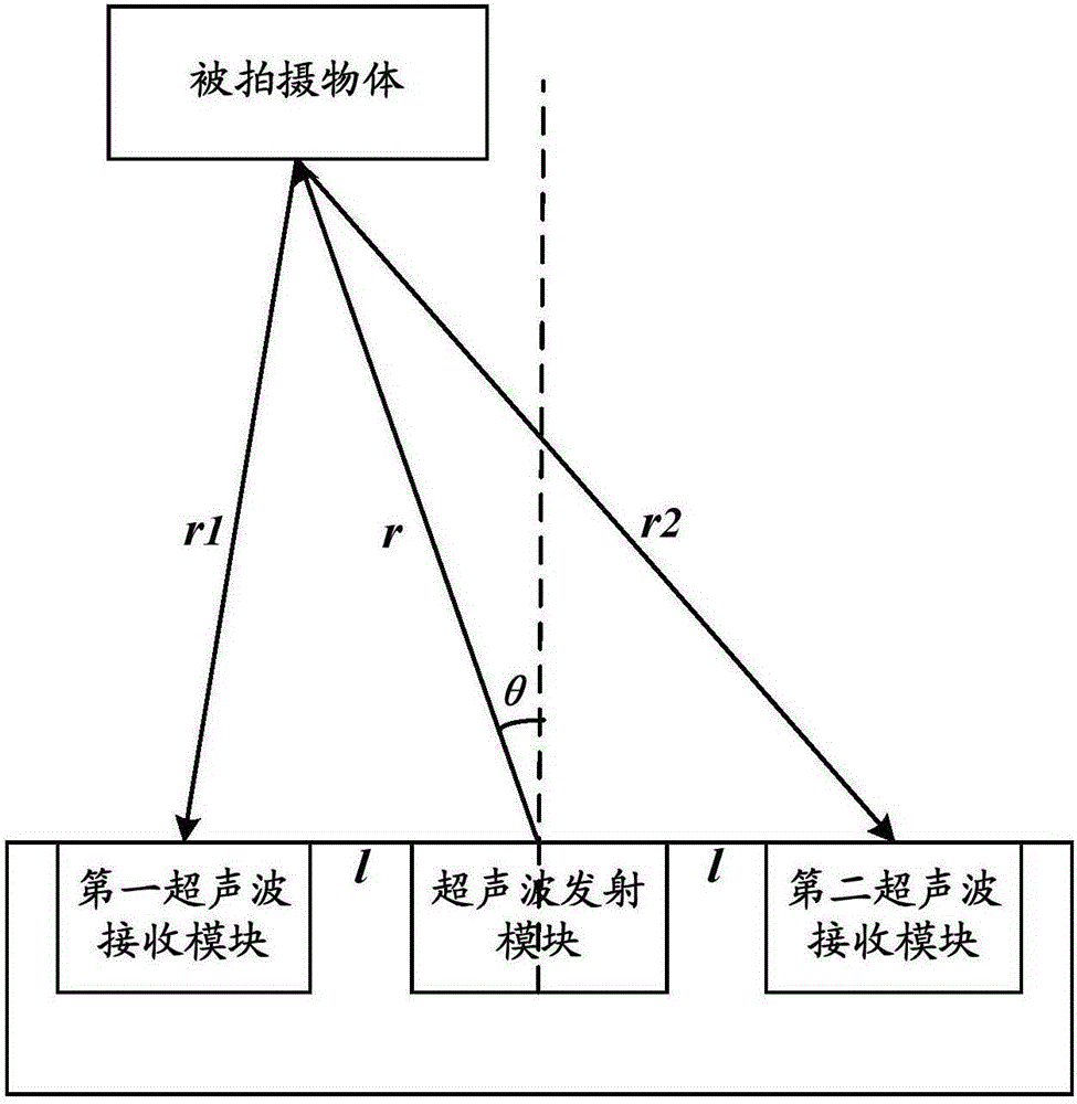
[0030] The ultrasonic transmitting module 101 has a first fixed distance d between the camera, and the ultrasonic transmitting module 101 is used to transmit ultrasonic waves toward the object to be photographed;

[0031] The ultrasonic receiving module 103 has a second fixed distance l between the ultrasonic transmitting module 101, and the ultrasonic receiving module 103 is used for receiving reflected ultrasonic waves reflected by the object to be photographed;

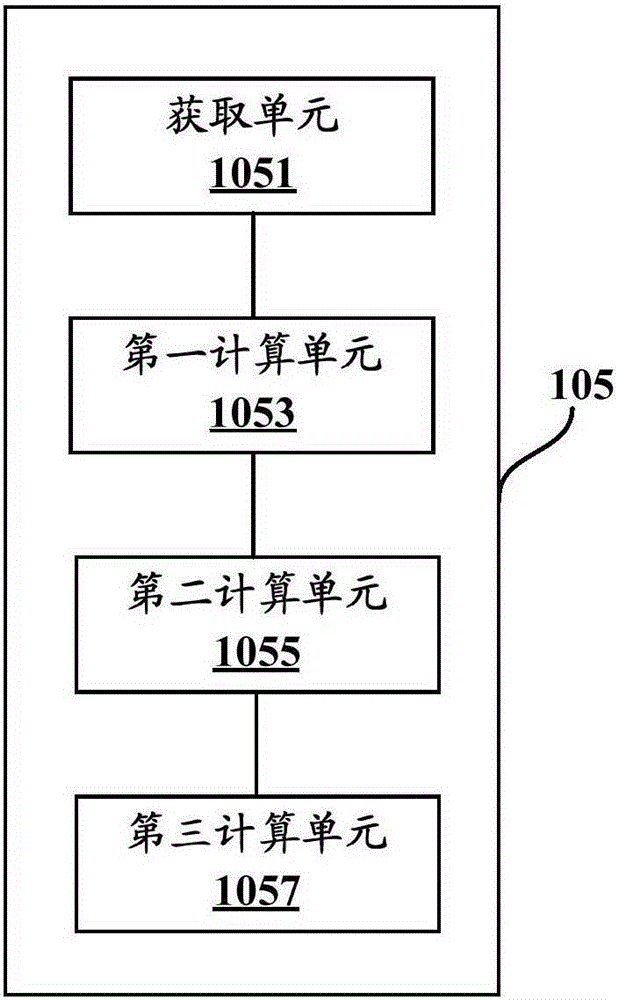
[0032] The calculation module 105 is used to calculate the time difference between the time when the ultrasonic receiving module receives the reflected ultrasonic waves and the time when the ultrasonic transmitting module emits ultrasonic waves towards the object to be photographed, and according to the time difference, the first fi...

Embodiment 2

[0072] According to another aspect of the present invention, a camera method is also provided, which is applied to the above-mentioned camera device, such as Figure 7 As shown, the camera method includes:

[0073] Step S701, acquiring the emission time when the ultrasonic emitting module emits ultrasonic waves toward the object to be photographed;

[0074] Step S703, obtaining the receiving time when the ultrasonic receiving module receives the reflected ultrasonic;

[0075] Step S705, calculate the time difference between the receiving time and the transmitting time, and according to the time difference, the first fixed distance d between the ultrasonic transmitting module and the camera, and the second fixed distance l between the ultrasonic receiving module and the ultrasonic transmitting module, Calculate the first distance s between the camera and the object to be photographed and the first included angle between the central axis of the camera and the line between the c...


PUM


Abstract

The present invention provides an imaging device and an imaging method. The imaging device comprises an ultrasonic wave emitting module which has a first fixed distance with a camera and is used for emitting ultrasonic wave to a shot object, an ultrasonic wave receiving module which has a second fixed distance with the ultrasonic wave emitting module and is used for receiving the reflecting ultrasonic wave reflected by the shot object, a calculation module which is used for calculating the time difference between the receiving time of receiving the reflecting ultrasonic wave and the emitting time of emitting the ultrasonic wave to a shot object, calculating and obtaining the first distance between the camera and the shot object and the angle formed by the central axis of the camera and the connection line between the camera and the shot object, and obtaining the position information of the shot object relative to the camera, and a focus shooting module for controlling the camera to carry out focus shooting on the shot object according to the position information. According to the imaging device and the imaging method, the detection of the information of the shot object is more accurate, and a user experience is improved.

Description

technical field [0001] The present invention relates to the technical field of imaging, in particular to an imaging device and an imaging method. Background technique [0002] In recent years, with the rapid development of the mobile terminal industry, its camera function has become a standard configuration, and it affects the user experience to a certain extent. Among them, the focus function is one of the factors affecting its camera function, and seriously affects the clarity of imaging. Among them, the so-called focusing refers to the process of changing the object distance and the distance position through the zoom mechanism to make the image of the object to be photographed clear. [0003] Generally, when an existing camera device automatically focuses, it first detects the object distance to the object to be photographed, and then adjusts the displacement of the camera according to the object distance to finally achieve focusing. However, during the above-mentioned ...

Claims


Application Information

Patent Timeline
Patent Type & Authority Applications(China)
IPC IPC(8): H04N5/232H04N5/225G03B13/36G03B30/00
Inventor 彭武
Owner VIVO MOBILE COMM CO LTD
Why Eureka
Eureka Blog
Learn More