
Programmable display

A display and indication technology, applied in the direction of static indicators, digital output to display equipment, instruments, etc., can solve the problem of not being able to properly hide technical know-how information

Active Publication Date: 2016-08-03
ORMON CORP
View PDF12 Cites 2 Cited by
  • Summary
  • Abstract
  • Description
  • Claims
  • Application Information

AI Technical Summary

Problems solved by technology

In the programmable display described in Patent Document 1, all display contents can be seen from all client computers regardless of their security level or importance, so know-how information cannot be properly concealed

Method used


Image

  • Programmable display
  • Programmable display
  • Programmable display

Examples


Embodiment Construction

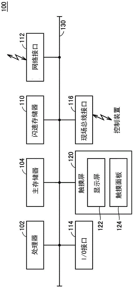
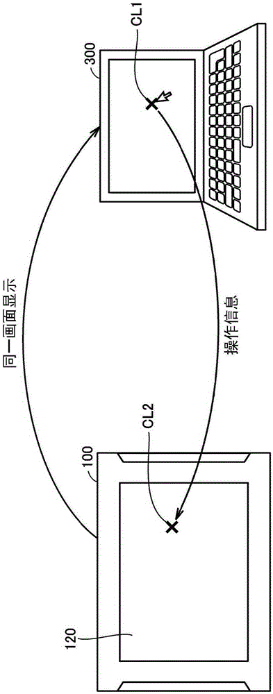
[0036] Embodiments of the present invention will be described in detail with reference to the drawings. In addition, the same code|symbol is attached|subjected to the same or corresponding part in a figure, and the description is abbreviate|omitted. In this embodiment, the control system 1 containing the programmable display 100 and the control apparatus 200 is demonstrated. However, the control system 1 demonstrated below is only an application example of the programmable display 100, and the technical scope of this invention should be reasonably interpreted based on description of a claim. In addition, in the following description, "the programmable display 100" is only described as "the display 100".

[0037]

[0038] First, the overall configuration of the control system 1 of the present embodiment will be described. figure 1 It is a schematic diagram which shows the whole structure of the control system 1 of this embodiment. refer to figure 1 , the control system 1 ...


PUM


Abstract

The invention provides a programmable display, and relates to a configuration that appropriately preserves the security level of a display content in the programmable display which allows remote viewing of the display content. The programmable display for connection to a control device includes: a user management unit configured to identify a user accessing the programmable display; a generation unit configured to generate an interface screen containing information from the control device in accordance with privileges assigned the user identified by the user management unit; a display unit configured to output the interface screen; a connection management unit configured to, in response to a request for access from a user on an external device, establish a connection with the external device on the basis of identification of the user by the user management unit, and to send the interface screen to an external device with which a connection is established; and the user management unit prohibits simultaneous access to the programmable display by a plurality of users each having different privileges assigned.

Description

technical field [0001] The present invention relates to a programmable display for browsing or operating a control system including a control device. Background technique [0002] In a general manufacturing site, a control device called a PLC (Programmable Logic Controller; Programmable Logic Controller) is used to control manufacturing devices, robots, and the like. With the demand for labor saving in the manufacturing site and the progress of ICT (Information and Communication Technology; information communication technology), etc., technologies for remote viewing or operation using network technology have been developed. [0003] For example, JP Unexamined Patent Publication No. 2008-33573 (Patent Document 1) discloses a configuration in which a screen displayed on a programmable display can be remotely displayed, and operations similar to those of the programmable display can be performed on the displayed screen. . More specifically, the programmable display of patent ...

Claims


Application Information

Patent Timeline
Patent Type & Authority Applications(China)
IPC IPC(8): G05B19/05
CPCG05B19/058G05B2219/14006G06F3/1454G06F21/31G06F21/62G06F21/84H04N1/4433G09G2358/00G06F21/445H04L63/08H04L63/104H04N1/00204H04N2201/0089G06F9/452H04L67/131G06F3/14H04L63/10
Inventor 永田雄大
Owner ORMON CORP
Learn More