
T-shaped beam column connecting joint

A technology for connecting nodes and shaped beams and columns, which is applied in the direction of architecture and building construction, can solve the problems of protruding corners and corners of column chambers, and achieve the goals of improving bearing capacity and ductility, strong restraint, increasing room use area and aesthetics Effect

Active Publication Date: 2016-08-03
XI'AN UNIVERSITY OF ARCHITECTURE AND TECHNOLOGY
View PDF6 Cites 10 Cited by
  • Summary
  • Abstract
  • Description
  • Claims
  • Application Information

AI Technical Summary

Problems solved by technology

[0006] The purpose of the present invention is to provide a T-shaped beam-column connection node with stiffening rib concrete-filled steel pipe composite columns with simple construction and low cost, which can solve the problem of protruding edges and corners in the traditional column chamber, and improve the bearing capacity of multi-cavity concrete-filled steel pipe composite columns. Ductility

Method used


Image

  • T-shaped beam column connecting joint
  • T-shaped beam column connecting joint
  • T-shaped beam column connecting joint

Examples


Embodiment Construction

[0030] The present invention will be described in further detail below in conjunction with specific embodiments.

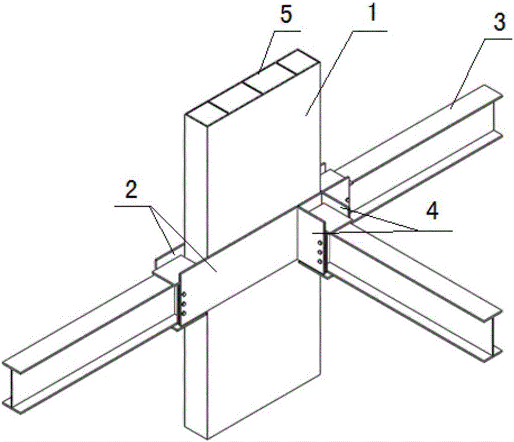
[0031] Such as figure 1 As shown, the T-shaped beam-column connection node of the present invention includes a multi-cavity steel pipe concrete composite column 1, and side plates 2 symmetrically arranged along the two side walls of the multi-cavity steel pipe concrete composite column 1, and a penetrating The side plate 2 is inserted into the inserting plate 4 of the multi-cavity steel pipe concrete composite column 1 inside it, and a reinforced H-shaped steel composite beam 3 is inserted on the extension of the two side plates 2 and the inserting plate 4 to form a T-shaped beam-column connection node.

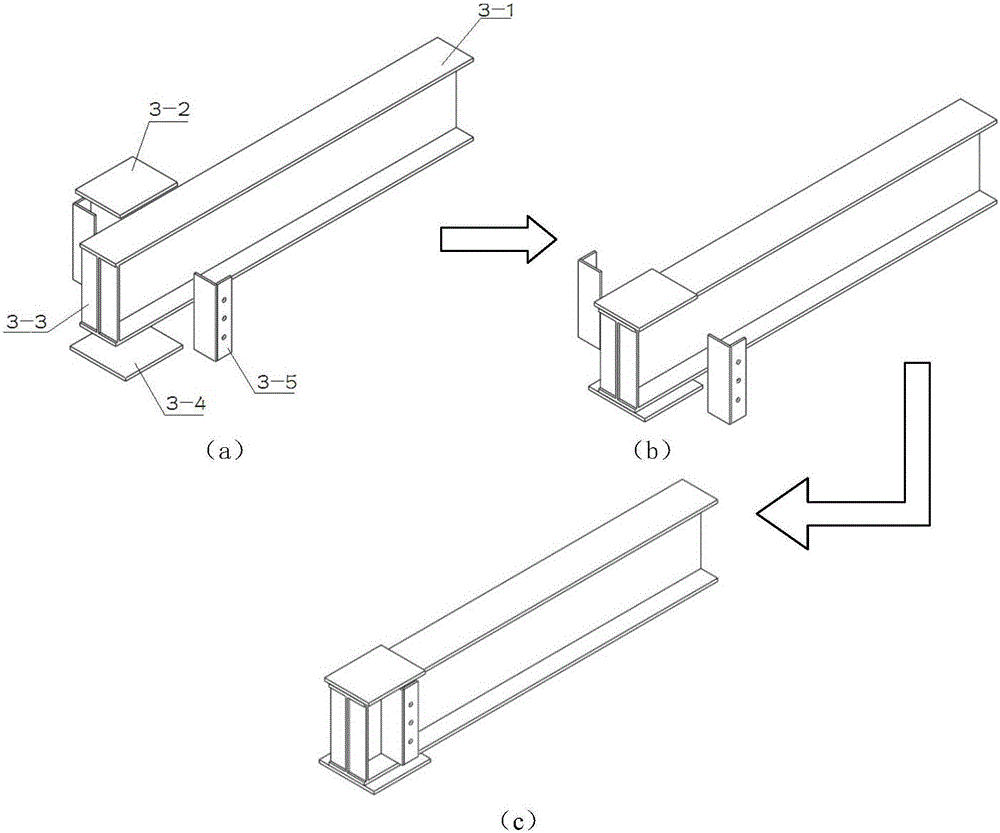
[0032] Such as figure 2 Shown in (a)-(c), the reinforced H-shaped steel composite beam 3 of the present invention includes H-shaped steel 3-1, and two stiffeners 3-1 arranged between the H-shaped steel 3-1 end steel flanges 3. The stiffener 3-3 is welded on bo...


PUM


Abstract

The invention discloses a T-shaped beam column connecting joint. The T-shaped beam column connecting joint comprises a multi-cavity concrete filled steel tube combined column and side plates symmetrically arranged at the two side walls of the multi-cavity concrete filled steel tube combined column, inserting plates which penetrate through the side plate and are inserted into the multi-cavity concrete filled steel tube combined column are arranged on one side plate, and a reinforcing H-shaped steel combined beam is inserted into extending sections of the two side plates and the inserting plate to form the T-shaped beam column connecting joint. The joint serves as an edge restraint member of the whole concrete filled steel tube column and can improve bearing capacity, energy-dissipating capacity and ductility of the concrete filled steel tube column; on-site construction is convenient, the multi-cavity concrete filled steel tube combined column is not damaged, and materials and labor are saved. A steel tube has a strong restraint effect on concrete, the whole structure conforms to the design rule of matching strong columns with weak beams and matching strong joints with weak members, the joint has multiple anti-seismic fortifying lines, it is avoided that a whole system is damaged as part of members are damaged, and the joint has necessary strength, good deformability and good energy-dissipating capacity.

Description

technical field [0001] The invention relates to a T-shaped beam-column connection node, which is mainly applied to the steel pipe concrete composite column of multi-storey and high-rise buildings in the building structure. Background technique [0002] With the economic globalization and the improvement of urbanization level, the urban population density is gradually increasing, which makes a large number of high-rise buildings emerge continuously. There is an urgent need for new technologies to support the design and construction of high-rise and multi-storey buildings. [0003] Concrete filled steel tube utilizes the interaction between the steel tube and concrete in the process of stress, that is, the restraint of the steel tube on the concrete makes the concrete in a complex stress state, so that the strength of the concrete is improved, and the plasticity and toughness are greatly improved. At the same time, after the steel pipe is filled with concrete, the buckling of...

Claims


Application Information

Patent Timeline
IPC IPC(8): E04B1/21E04B1/58
CPCE04B1/1903E04B1/215E04B1/58
Inventor 郝际平孙晓岭张伟薛强樊春雷黄育琪刘斌陈永昌王磊尹伟康刘瀚超何梦楠张峻铭赵子健
Owner XI'AN UNIVERSITY OF ARCHITECTURE AND TECHNOLOGY
Learn More