Split-screen image display method and device
An image display device and image display technology are applied in image communication, electrical components, stereoscopic systems, etc., which can solve problems such as frequent removal and wearing of 3D glasses, and achieve the effect of increasing complexity
- Summary
- Abstract
- Description
- Claims
- Application Information
AI Technical Summary
Problems solved by technology
Method used
Image

Examples
Embodiment 1
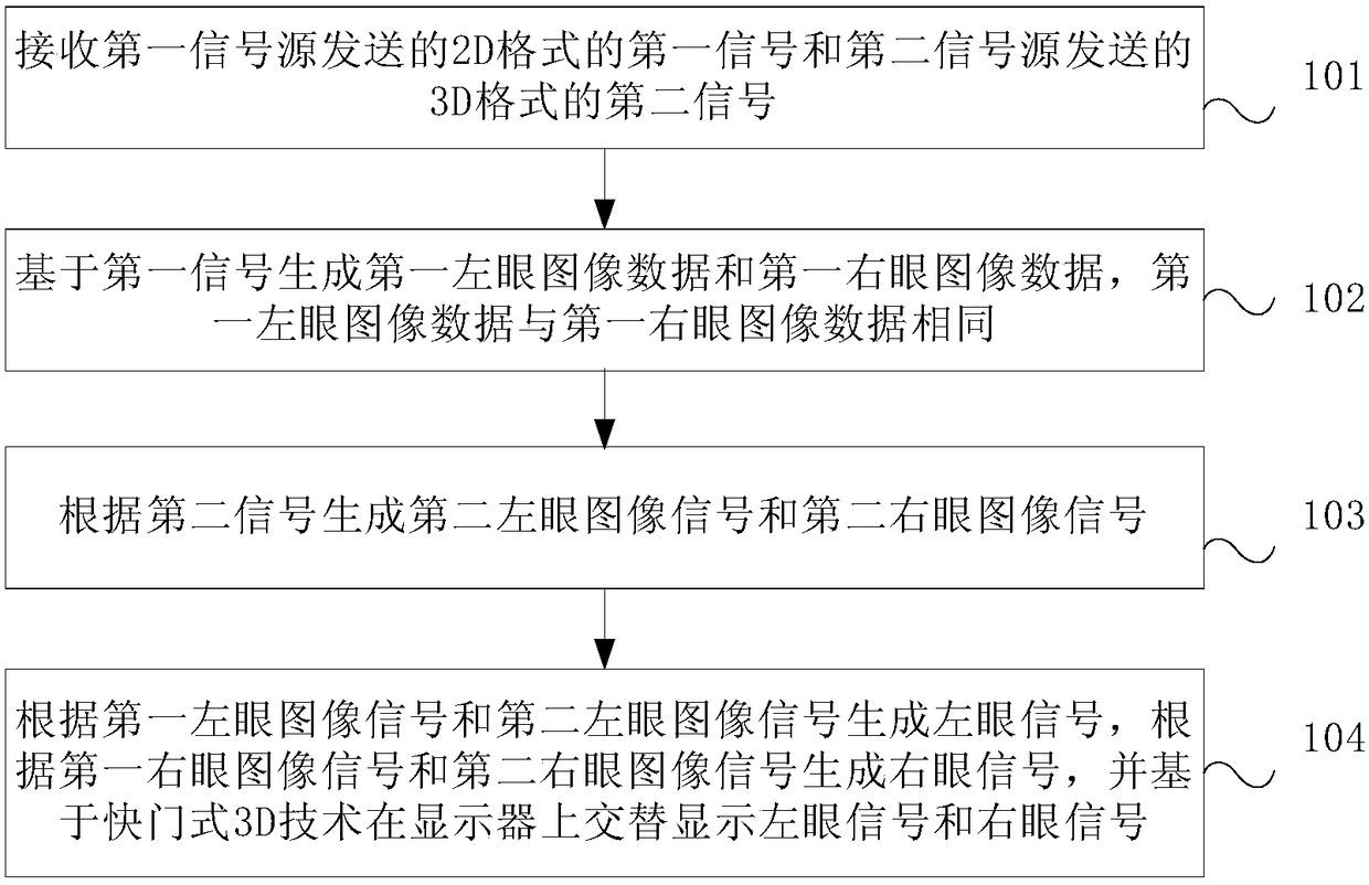
[0025] This embodiment provides a split-screen image display method. The split-screen image display method is used in split-screen display, that is, images from different signal sources are simultaneously displayed in different display areas on one display. The display is at least capable of displaying 3D images. The executor of this embodiment is a split-screen image display device, and the split-screen image display device may be various terminals, such as medical equipment, computers, IPads, mobile terminals, and the like.
[0026] The split-screen image display method in this embodiment is based on the shutter-type 3D technology for display. The 3D glasses based on the shutter 3D technology mainly realize the 3D effect by increasing the fast refresh rate of the picture (usually up to 120Hz), which belongs to the active 3D technology, and is also called time-sharing shading technology or liquid crystal time-sharing technology. Specifically, when the 3D signal is input to t...
Embodiment 2
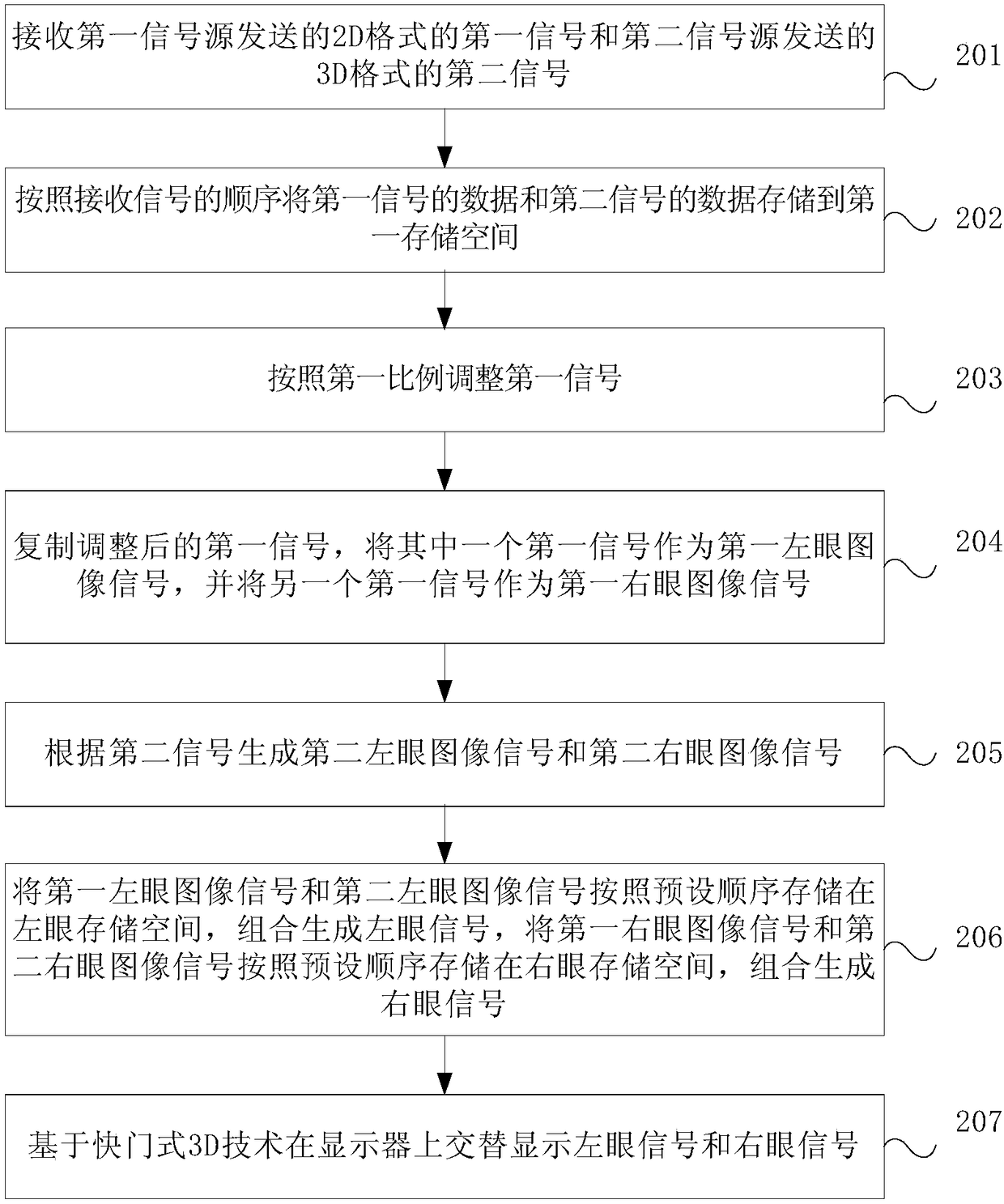
[0046] In this embodiment, a further supplementary explanation is given for the split-screen image display method in Embodiment 1. In this embodiment, the original signals of different signal sources need to be processed first, and then the first left-eye image data, the first right-eye image data, the second left-eye image data and the second right-eye image data are generated, according to the first left-eye image data generating a left-eye image signal from the image data and the second left-eye image data, generating a right-eye image signal from the first right-eye image data and the second right-eye image data, and alternately displaying the left-eye image signal on the display based on a shutter type 3D technology and the right-eye image signal.
[0047] Such as figure 2 As shown in FIG. 2 , it is a schematic flowchart of a split-screen image display method according to this embodiment. The flow display method of this embodiment includes:
[0048] Step 201, receivin...
Embodiment 3
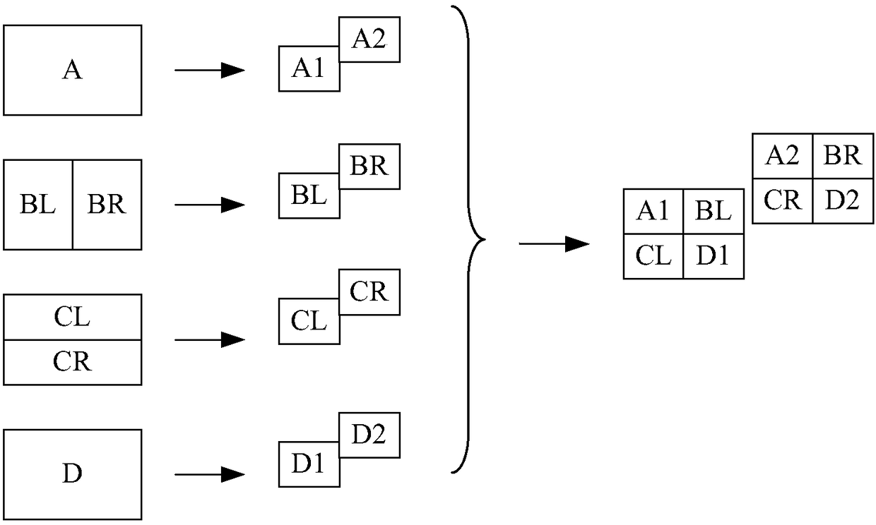
[0071] In this embodiment, a four-channel split-screen display is taken as an example for specific description. That is, one display is divided into four display areas, and images from four signal sources are displayed respectively, and each image occupies a quarter of the display area. The resolution of the display is X*Y, where X is the number of effective pixels in each line of the display, and Y is the number of effective image lines contained in one frame of image.
[0072] Such as Figure 3A As shown, it is assumed that channels A, B, C, and D correspond to different signal sources, the image resolution of the signals of each channel is X*Y, and the signal refresh frequency is 60Hz. Among them, the signal sources corresponding to channels A and D send 2D signals, and the corresponding images are A and D respectively, and the signal sources corresponding to channels B and C send 3D signals. Specifically, the 3D signal format of channel B is The side-by-side (SBS, left a...
PUM
 Abstract
Description
Claims
Application Information
 - Generate Ideas
- Intellectual Property
- Life Sciences
- Materials
- Tech Scout
- Unparalleled Data Quality
- Higher Quality Content
- 60% Fewer Hallucinations
Browse by: Latest US Patents, China's latest patents, Technical Efficacy Thesaurus, Application Domain, Technology Topic, Popular Technical Reports.
© 2025 PatSnap. All rights reserved.Legal|Privacy policy|Modern Slavery Act Transparency Statement|Sitemap|About US| Contact US: help@patsnap.com