An automatic lock for a character-eight door
What is Al technical title?
Al technical title is built by PatSnap Al team. It summarizes the technical point description of the patent document.
A figure-eight door and automatic locking technology, which is applied to building locks, fastening devices of wing sashes, and building fastening devices, etc., can solve problems such as troublesome opening and closing, poor safety, etc., to ensure safety, avoid transitional movement, The effect of convenient directional movement
Active Publication Date: 2018-03-06
宜宾安帛达建设工程有限公司
View PDF4 Cites 0 Cited by
Summary
Abstract
Description
Claims
Application Information
AI Technical Summary
This helps you quickly interpret patents by identifying the three key elements:
Problems solved by technology
Method used
Benefits of technology
Problems solved by technology
Most of the existing eight-character door locks use artificial iron chains and padlocks to connect and lock the main door and the auxiliary door. This connection structure is troublesome to open and close, and the safety is poor
Method used
Image
Click on the blue label to locate the original text in one second.
Reading with bidirectional positioning of images and text.
Examples
Embodiment Construction
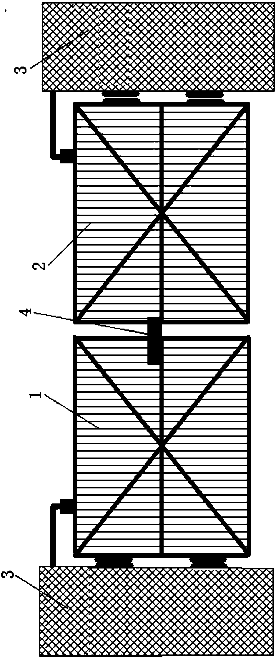
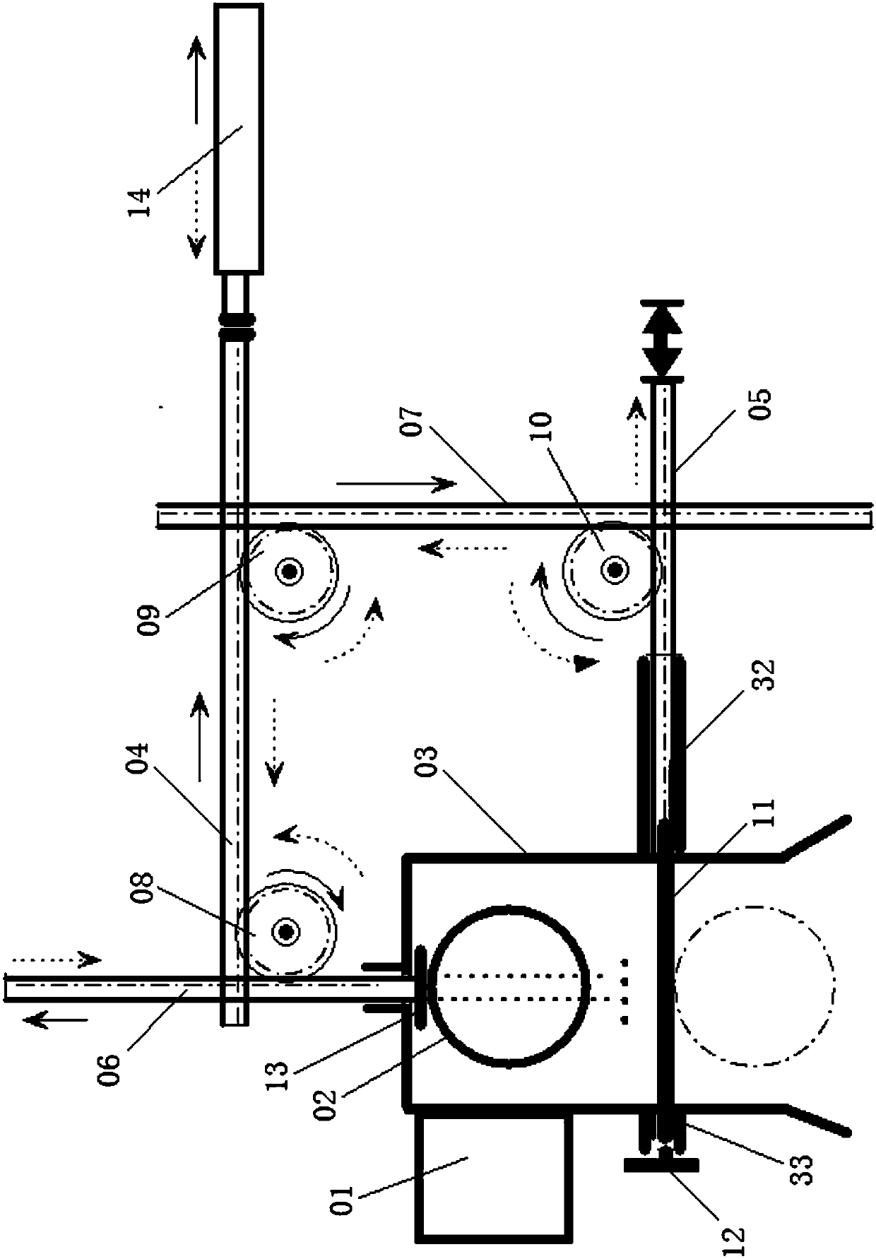
[0017] See figure 2 , a kind of eight-character door automatic lock, wherein, the eight-character door includes main door 1 and auxiliary door 2 (see figure 1 ); the eight-character door automatic lock 4 includes the auxiliary door post 02 arranged on the auxiliary door 2, the main door post 01 arranged on the main door 1, the U-shaped lock groove 03, the first horizontal rack 04, the second horizontal tooth bar Bar 05, first vertical rack 06, second vertical rack 07, first transmission gear 08, second transmission gear 09, third transmission gear 10 and locking bar 11;
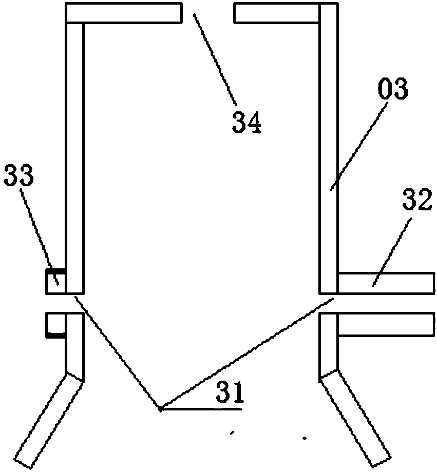
[0018] The main doorpost 01 is fixedly provided with a U-shaped lock groove 03, and the two ends of the U-shaped lock groove 03 are opening structures in a figure-eight shape, and the two vertical parts of the U-shaped lock groove 03 are provided with relative lock holes 31 (see image 3 ), the outer walls of the two vertical parts of the U-shaped lock groove 03 and the periphery of the corresponding lock h...
PUM
Abstract
The invention discloses an automatic lock of a splayed door. The automatic lock comprises an auxiliary door post, a main door post, a U-shaped lock groove, a first horizontal rack, a second horizontal rack, a first vertical rack, a second vertical rack, a first transmission gear, a second transmission gear, a third transmission gear and a lock bar, wherein the first horizontal rack, the second horizontal rack, the first vertical rack, the second vertical rack, the first transmission gear, the second transmission gear and the third transmission gear form a transmission structure and are in mutual engagement transmission. According to the automatic lock, one rack is pushed through the auxiliary door post, the rack pushes the lock bar into the lock groove under the transmission action of the transmission racks and the other racks, and the door is quickly locked, the transmission structure guarantees the safety of the lock, and people cannot easily damage the lock; and one rack is pushed through a one-way electric rack, on one hand, the rack pushes the auxiliary door post back to the original position through the transmission action of the transmission racks and the other racks, one the other hand, the rack pulls out the lock bar, and the door is quickly opened.
Description
technical field [0001] The invention relates to the field of door locks, in particular to an automatic lock for a character-eight door. Background technique [0002] See figure 1 , the eight-character door includes a main door 1 and an auxiliary door 2, the vertical outer sides of the main door 1 and the auxiliary door 2 are respectively hinged with the corresponding columns 3, and the vertical inner sides of the main door 1 and the auxiliary door 2 are closely fitted, and through pushing and pulling The main door 1 and the auxiliary door 2 realize the opening and closing of the door. The lockset of existing figure-of-sight gate mostly adopts artificial iron chain and padlock to connect and lock the main door and the auxiliary door. This connection structure is troublesome to open and close, and the safety is relatively poor. Contents of the invention [0003] The technical problem to be solved by the present invention is to provide an automatic lock for a figure-eight d...
Claims
Application Information
Patent Timeline
Application Date:The date an application was filed.
Publication Date:The date a patent or application was officially published.
First Publication Date:The earliest publication date of a patent with the same application number.
Issue Date:Publication date of the patent grant document.
PCT Entry Date:The Entry date of PCT National Phase.
Estimated Expiry Date:The statutory expiry date of a patent right according to the Patent Law, and it is the longest term of protection that the patent right can achieve without the termination of the patent right due to other reasons(Term extension factor has been taken into account ).
Invalid Date:Actual expiry date is based on effective date or publication date of legal transaction data of invalid patent.