Method and system for detection and parameter estimation of chirp signal
A technology of linear frequency modulation signal and detection method, applied in the field of signal processing, can solve problems such as huge total calculation amount, and achieve the effects of reducing coordinate transformation, improving discrete calculation speed, and improving performance
- Summary
- Abstract
- Description
- Claims
- Application Information
AI Technical Summary
Problems solved by technology
Method used
Image
Examples
Embodiment
[0105] at sampling frequency f s =8000Hz Sampling the continuous signal of the following form, the time domain and frequency domain waveforms of the obtained signal are as follows Figure 6 shown, where Figure 6 -(a) is the time domain waveform of the signal, Figure 6 -(b) is the spectrum distribution of the signal.
[0106]
[0107] Which contains the chirp signal exp[jπf 0 t+πBt 2 ], the parameters of the chirp signal are as follows: the center frequency is f 0 =200Hz, the signal bandwidth is B=200Hz, the signal pulse width is T=0.1s, k=B / T is the frequency modulation slope of the signal, for the linear frequency modulation signal, k=2000. n(t) is noise, and the signal-to-noise ratio of the chirp signal and the noise is SNR=-10dB. It can be seen from the time domain and frequency domain waveforms in Figure (6) that the chirp signal is completely submerged in noise.
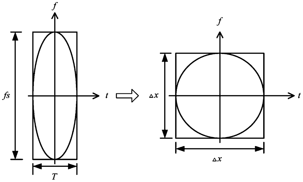
[0108] 1. Dimensional normalization processing is performed on the signal, and the normalization ...
PUM
 Abstract
Description
Claims
Application Information
 - R&D Engineer
- R&D Manager
- IP Professional
- Industry Leading Data Capabilities
- Powerful AI technology
- Patent DNA Extraction
Browse by: Latest US Patents, China's latest patents, Technical Efficacy Thesaurus, Application Domain, Technology Topic, Popular Technical Reports.
© 2024 PatSnap. All rights reserved.Legal|Privacy policy|Modern Slavery Act Transparency Statement|Sitemap|About US| Contact US: help@patsnap.com


