Coupled linear direct drive float type wave energy generation device

A power generation device, float type technology, applied in ocean energy power generation, engine components, machines/engines, etc., can solve the problems of high natural frequency, severe float vibration, and excessive voltage.

Active Publication Date: 2018-05-18
SHANGHAI JIAOTONG UNIV
View PDF6 Cites 0 Cited by
  • Summary
  • Abstract
  • Description
  • Claims
  • Application Information

AI Technical Summary

Problems solved by technology

[0004] In order to solve the problems of high natural frequency of the current wave energy generating device, severe vibration of the float during resonance and excessive voltage generated during resonance, the present invention provides a wave energy generating device

Method used


Image

  • Coupled linear direct drive float type wave energy generation device
  • Coupled linear direct drive float type wave energy generation device

Examples


Embodiment approach 1

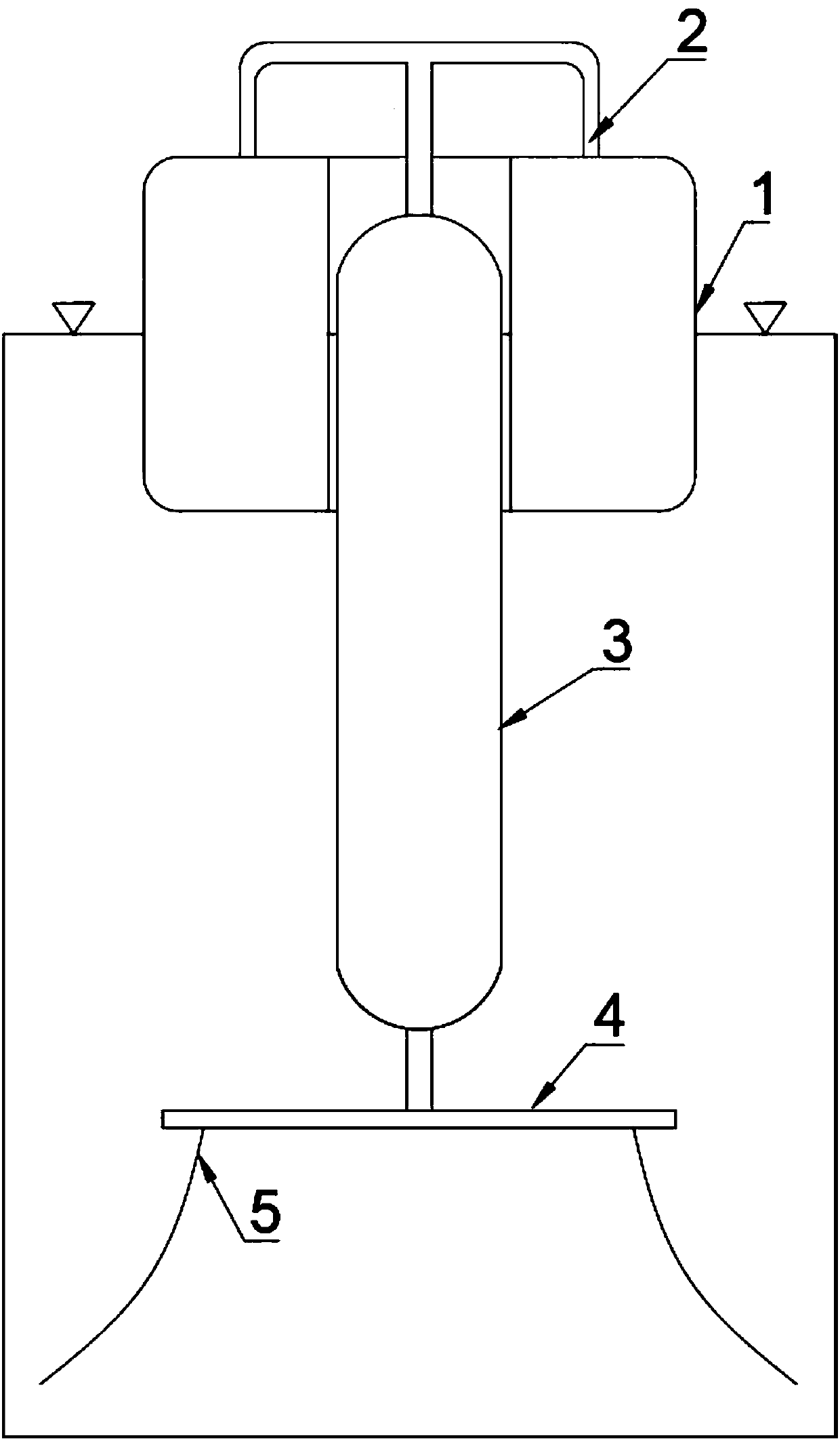
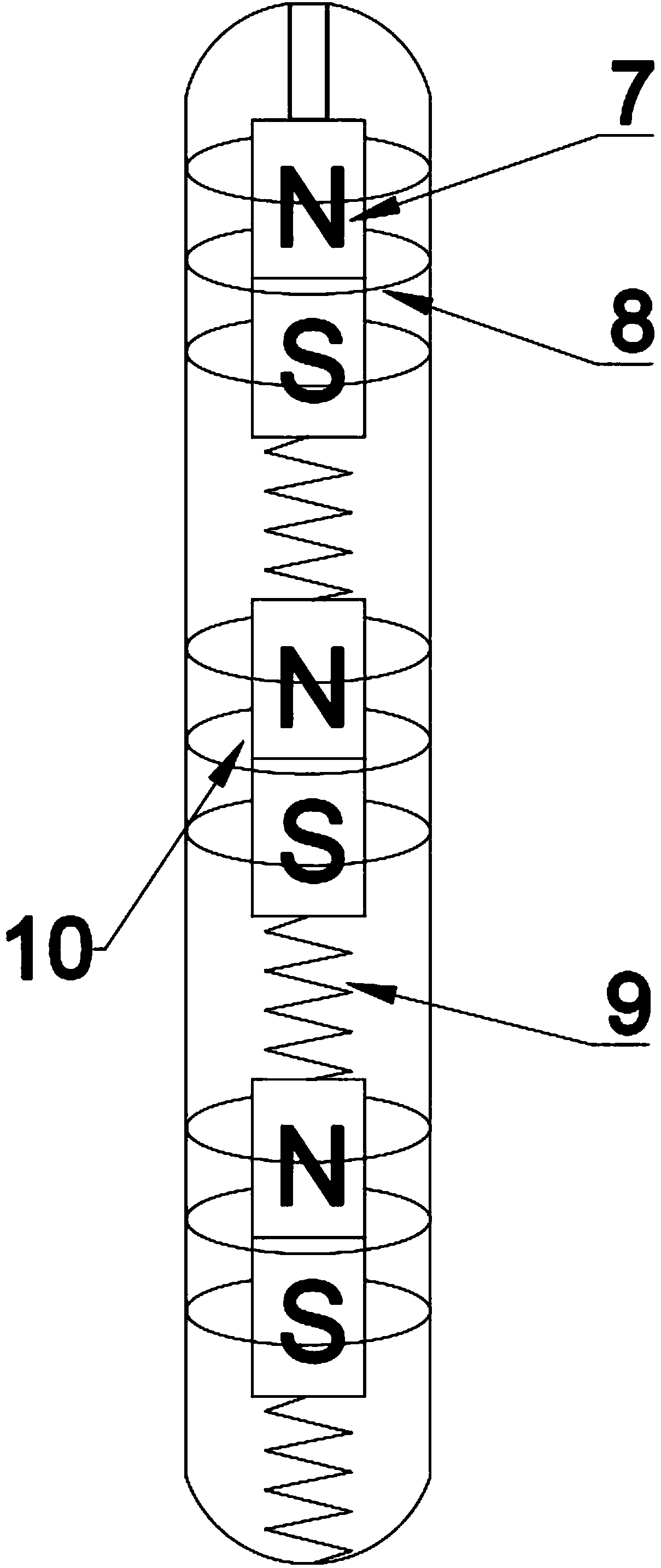
[0024] The first embodiment of the present invention provides a coupled linear direct-drive buoy type wave energy generating device, which includes a base, which is a heave plate 4 fixed in the sea by several anchor lines. The columnar generating device 3 is fixed on the upper surface of the heave plate 4, and a through hole for the connecting shaft 2 to pass is provided on the top of the columnar generating device 3, a seal is also provided on the through hole, and the seal is sleeved On the connecting shaft 2, the connecting shaft 2 can slide up and down relative to the sealing member. A plurality of magnets 7 are arranged inside the columnar generator 3, and the magnets 7 are arranged vertically in sequence to form a straight line, and the N poles of the magnets 7 point to the top or bottom of the columnar generator. Two adjacent magnets 7 are connected to each other by an elastic member, which can be a spring 9, or an elastic connecting member such as a rubber band. The m...


PUM


Abstract

The invention provides a coupling linear direct-driven floater type wave energy power generation device. The coupling linear direct-driven floater type wave energy power generation device comprises a base. A columnar power generation device is fixedly arranged on the upper surface of the base. A through hole for a connecting shaft to pass through is formed in the top of the columnar power generation device. The base is fixed in the sea. The columnar power generation device internally comprises a plurality of magnets and surrounding coils. The magnets are sequentially arranged vertically. The pole N of each magnet points at the top or the bottom of the columnar power generation device. Every two adjacent magnets are connected through an elastic piece, the bottommost magnet is fixedly connected with the bottom of the columnar power generation device through an elastic piece, the uppermost magnet is connected with a floater through a connecting shaft, and the induction coils are wound around the magnets and fixed to the columnar power generation device. The two ends of each induction coil are connected with a power storage device or a power utilization device. Waves drive the floater to vertically move and then drive the magnets to vertically move. According to the power generation device, the function of wave energy power generation is achieved in the manner that the magnets cut a magnetic field line.

Description

technical field [0001] The invention belongs to the field of novel renewable energy technology and marine equipment, in particular to a float type wave energy generating device. Background technique [0002] At present, the power generation methods mainly include wind power generation, water power generation, wave power generation and so on. Compared with wind energy, wave energy is a more durable and more energy-dense clean energy. If it can be effectively developed, it will provide human beings with sufficient and abundant clean energy. According to different energy conversion methods, wave energy generating devices can be divided into oscillating float type, oscillating water column type and shrinking ramp type. The oscillating buoy type wave energy power generation device is a well-developed energy conversion device at present. The device mainly uses the heave motion of the float to absorb wave energy, convert the wave energy into mechanical energy or hydraulic energy a...

Claims


Application Information

Patent Timeline
Patent Type & Authority Patents(China)
IPC IPC(8): F03B13/18
CPCF03B13/1845F05B2220/7068Y02E10/30
Inventor 肖龙飞肖晓龙彭涛杨立军李扬
Owner SHANGHAI JIAOTONG UNIV
Why Eureka
Try Eureka