Automatic tool changing spindle device of PCB edge drilling and milling machine

A technology of automatic tool change and PCB board, applied in positioning devices, metal processing mechanical parts, clamping and other directions, which can solve problems such as low efficiency

Inactive Publication Date: 2016-07-20
HUZHOU KEDA CHEM FUEL
View PDF6 Cites 7 Cited by
  • Summary
  • Abstract
  • Description
  • Claims
  • Application Information

AI Technical Summary

Problems solved by technology

The tool changing device in the prior art is a manual tool

Method used


Image

  • Automatic tool changing spindle device of PCB edge drilling and milling machine
  • Automatic tool changing spindle device of PCB edge drilling and milling machine
  • Automatic tool changing spindle device of PCB edge drilling and milling machine

Examples


Embodiment Construction

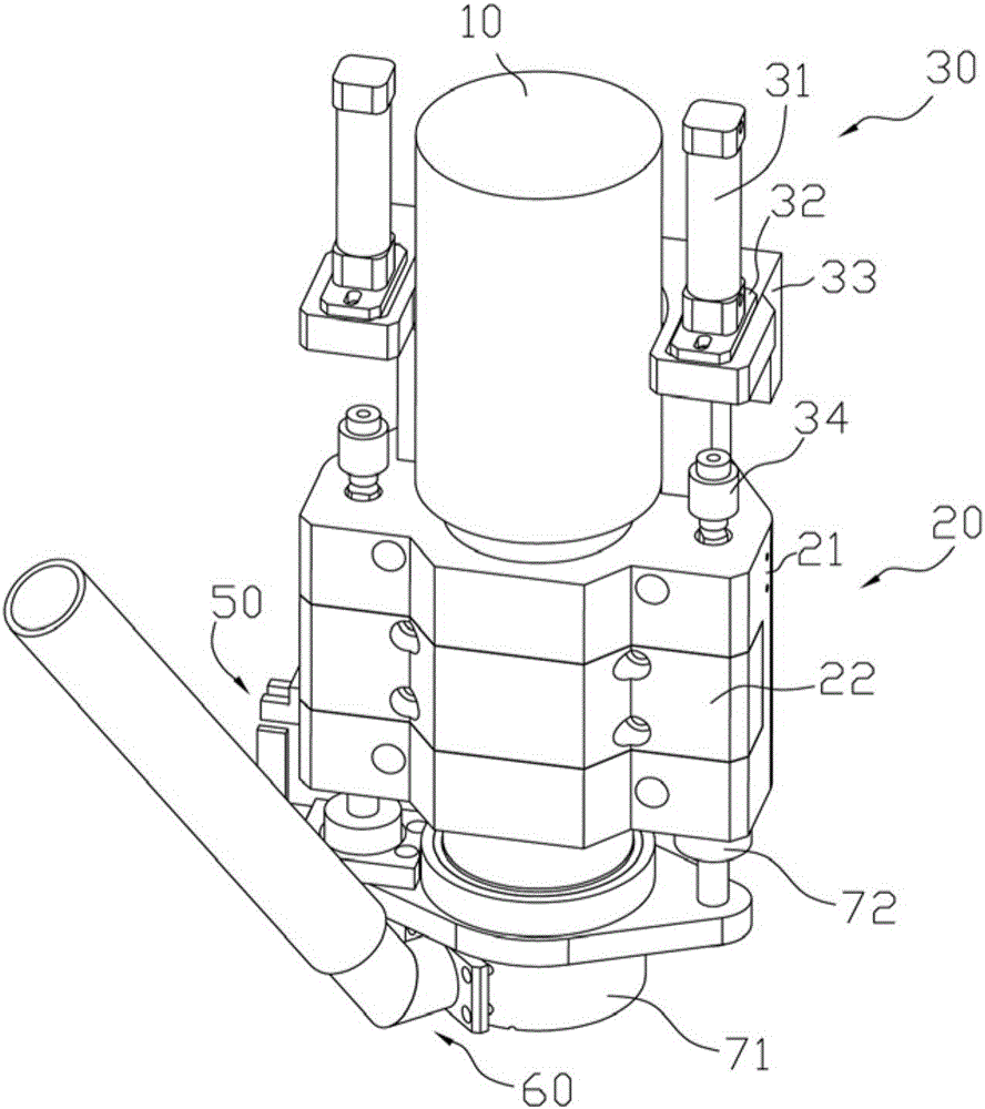
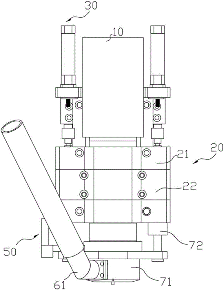
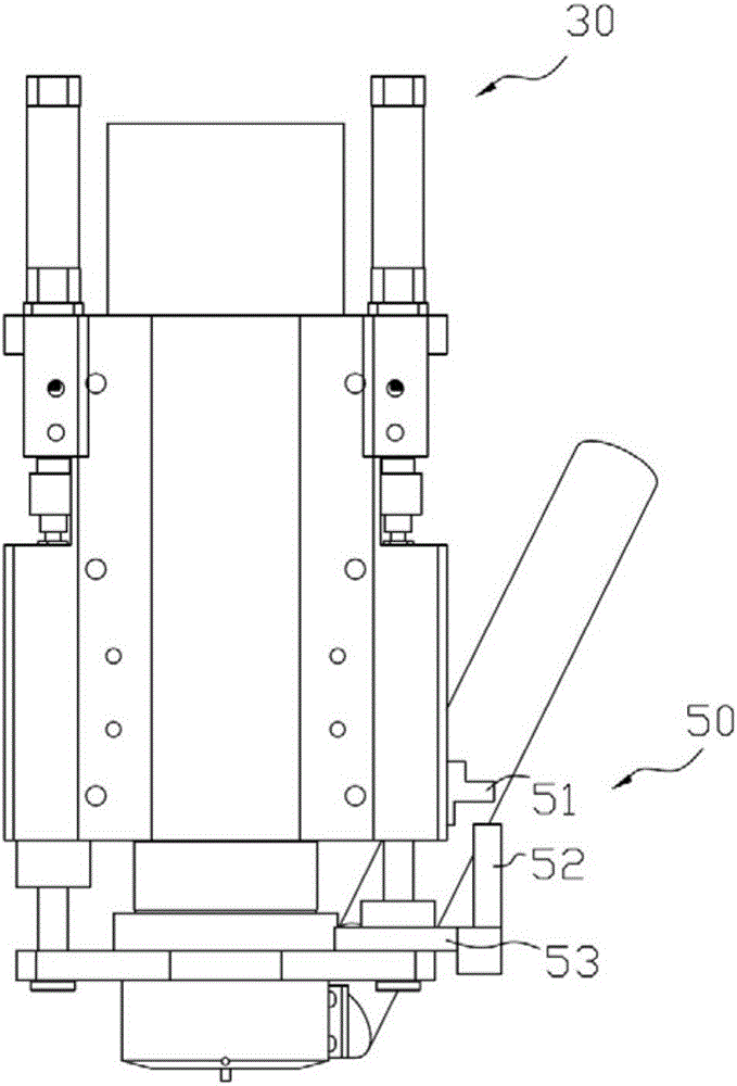
[0022] Such as Figure 1 to Figure 6 , an automatic tool changing spindle device for a PCB board gong edge machine,

[0023] An automatic tool change spindle device for a PCB edge machine, comprising a spindle 10, a clamp block 20, a cylinder assembly 30, a guide rod assembly 40, an induction assembly 50, a dust suction assembly 60 and a presser foot assembly 70; the spindle 10 wears It is installed through the center hole 210 of the clamp block 20, and the center line of the main shaft 10 coincides with the center line of the center hole 210 of the clamp block 20; it is characterized in that: a group of guide rod assemblies 40 are respectively installed on both sides of the symmetrical plane of the clamp block 20, and the The guide rod assembly 40 includes a guide rod 41 located in the clamp block 20, a linear bearing 42 close to the guide rod 41, and a guide rod fixing ring 43 screwed to the bottom of the guide rod 41. The upper end surface of the guide rod fixing ring 43 is...


PUM


Abstract

The invention discloses an automatic tool changing spindle device of a PCB edge drilling and milling machine. The automatic tool changing spindle device comprises a spindle, a clamping block, air cylinder assemblies, guide rod assemblies, an induction assembly, a dust collection assembly and a press foot assembly; the spindle penetrates a central hole of the clamping block to be mounted, and the center line of the spindle coincides with the center line center hole of the clamping block; the two sides of the symmetric face of the clamping block are each provided with one guide rod assembly, and each guide rod assembly comprises a guide rod located in a clamping block guide rod hole and a linear bearing tightly attached to the guide rod; the air cylinder assemblies are arranged over the guide rods, and the press foot assembly is arranged under the guide rods; air cylinder flotation joints of the air cylinder assemblies can be inserted into round holes in the tops of the guide rods to be in interference fit with the guide rods, and the spindle is in interference fit with a press foot table of the press foot assembly; and accordingly, air cylinders can drive the guide rods, the press foot assembly and the spindle to vertically move in the clamping block to achieve automatic tool changing work.

Description

Technical field: [0001] The invention relates to the technical field of PCB board processing, in particular to an automatic tool changing spindle device of a PCB board edge machine. Background technique: [0002] In the production process of PCB circuit boards, the gong edge machine is mainly used to drill small round holes on the circuit board. The main shaft device of the gong edge machine is the main processing part of the drilling machine, which is composed of the main shaft and the main shaft fixture. The lower part of the spindle is the processing tool. The tool changing device in the prior art is a manual tool changing, which has low efficiency and needs to be improved. Invention content: [0003] The purpose of the present invention is to provide a new automatic tool change spindle device for PCB board edge machine, which has the characteristics of fast tool change speed and high production efficiency. [0004] To achieve the above object, the technical scheme ad...

Claims


Application Information

Patent Timeline
IPC IPC(8): B23B19/02B23Q11/00B23Q3/157
CPCB23Q1/70B23Q3/15713B23Q11/0046
Inventor 董荣琴
Owner HUZHOU KEDA CHEM FUEL
Why Eureka
Try Eureka