
Metro station foundation pit construction method for controlling deformation of neighboring buildings

A technology for subway stations and construction methods, applied in construction, infrastructure engineering, excavation, etc., can solve the problems of enclosure wall deformation, large surface settlement, and difficulty in protecting adjacent buildings, and reduce the offset of enclosure walls Effect

Inactive Publication Date: 2016-07-13
SHANDONG UNIV OF TECH
View PDF5 Cites 12 Cited by
  • Summary
  • Abstract
  • Description
  • Claims
  • Application Information

AI Technical Summary

Benefits of technology

This technology uses an improved way to construct underground structures without causing issues like settling or tilting nearby houses due to their lack of sturdy supporting walls at certain points along its length. It achieves this through careful planning based upon the strength of the surrounding materials used while excavating around it's corner.

Problems solved by technology

The technical problem addressed by this patented technology relates to improving the stability and durability of underground structures such as railway stations without causing damage during construction due to subsidence caused by soil movement around them.

Method used


Image

  • Metro station foundation pit construction method for controlling deformation of neighboring buildings
  • Metro station foundation pit construction method for controlling deformation of neighboring buildings
  • Metro station foundation pit construction method for controlling deformation of neighboring buildings

Examples


Embodiment Construction

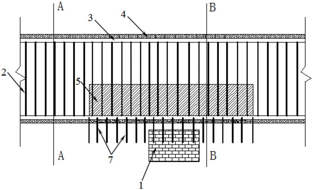
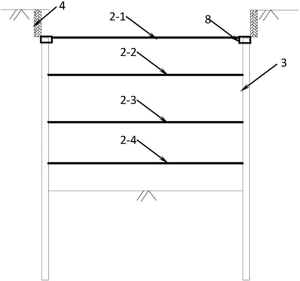
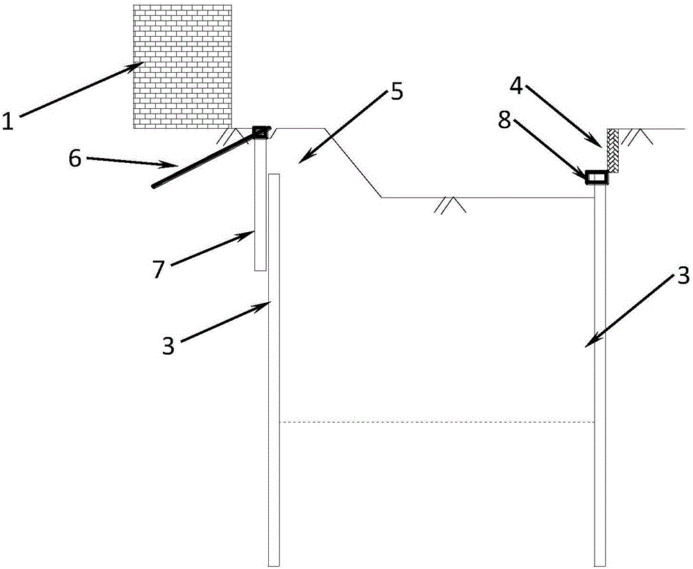
[0030] The present invention will be further described below in conjunction with the accompanying drawings and embodiments.

[0031] Such as figure 1 , figure 2 , image 3 As shown, the positional relationship between the foundation pit of the station and the adjacent building 1 is constructed according to the conventional method. Local construction isolation pile 6, the effect of isolation pile 6 is to protect building; On isolation pile 6, construct anchor rod 7 and apply prestress; Excavate foundation pit soil mass then, but keep the soil mass 5 closer to building 1 , construct the retaining wall 4 at the position where the top of the foundation pit enclosure wall 3 is exposed during the excavation, to support the deformation of the upper soil body; and pour the enclosure wall crown beam 8 on the top of the foundation pit enclosure wall 3 to increase the foundation pit The stiffness of the retaining wall 3; next, the supporting support 2 will be supported in the foundat...


PUM


Abstract

The invention discloses a metro station foundation pit construction method for controlling deformation of neighboring buildings. The method comprises the following steps: constructing a foundation pit enclosure wall; digging a foundation pit soil body in a manner of retaining a soil body to be closer to the buildings; horizontally placing a first layer of steel struts in a pressing manner below the reserved soil body; digging the reserved soil body; pouring a metro station top plate on the surface of the soil with an upper part excavated to be flat; after concrete of the top plate reaches designed strength, removing a template, laying a top plate waterproof material, and backfilling soil to recover the pavement; continuously and horizontally placing a second layer of steel struts at a designed height below the top plate; digging the soil body continuously according to the designed height; horizontally pressing a third layer of steel struts at the designed height, and applying pre-stress; digging the soil body continuously according to the designed height; horizontally pressing a fourth layer of steel struts at the designed height, and applying press-stress; digging the soil body to the bottom of the foundation pit, flattening the surface of the soil, and pouring a station base plate; constructing edge walls and middle plates of station according to a sequential method, and removing the steel struts in sequence from bottom to top in the process of upwards constructing the edge walls, to complete a civil engineering structure of the station.

Description


Claims


Application Information

Patent Timeline
Owner SHANDONG UNIV OF TECH
Learn More