
A friction stir welding laser calibration device and calibration method

A friction stir welding and calibrating device technology, which is applied in welding equipment, non-electric welding equipment, metal processing equipment, etc., can solve problems such as inability to achieve surface welding of complex workpieces, difficulty in ensuring consistency of weld strength, and complex shapes of areas to be welded , to achieve the effects of simple structure, improved welding quality and strong practicability

Active Publication Date: 2017-11-17
常熟市知识产权运营中心有限公司
View PDF1 Cites 0 Cited by
  • Summary
  • Abstract
  • Description
  • Claims
  • Application Information

AI Technical Summary

Problems solved by technology

Although high-quality welded joints can be obtained by using the friction stir welding method, in actual engineering operations, the shape of the area to be welded is complex, and the traditional lathe-type friction stir welding is severely limited. It can only weld flat surfaces and cannot achieve complex workpiece surfaces. welding
Due to the complexity of the workpiece, the position of the welding tool needs to be changed and calibrated in time during welding, as described in the patent (application number 201510675554.6), but this calibration method has a small scope of application, and requires cumbersome preparations before welding. The equipment is huge and it is difficult to ensure the weld seam The strength consistency before and after is difficult to achieve on general friction stir welding equipment

Method used


Image

  • A friction stir welding laser calibration device and calibration method
  • A friction stir welding laser calibration device and calibration method
  • A friction stir welding laser calibration device and calibration method

Examples


Embodiment Construction

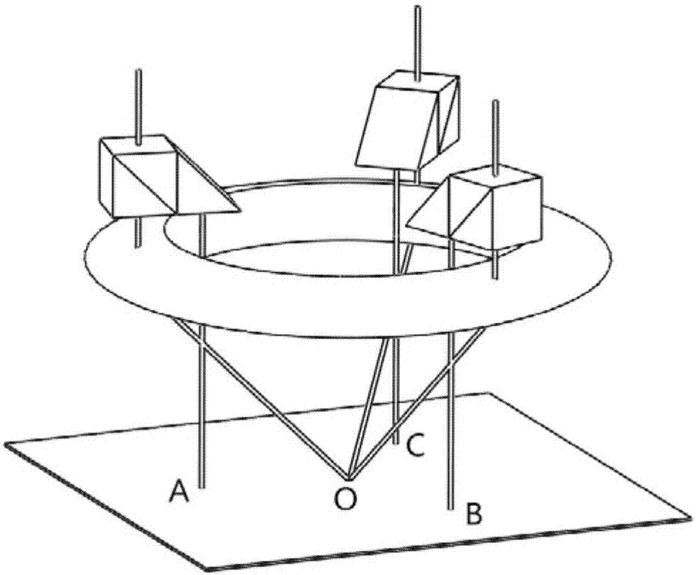
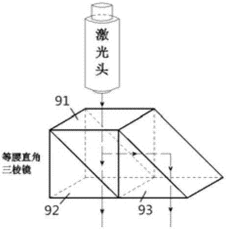
[0023] like Figure 1 to Figure 3 As shown, a friction stir welding laser calibration device of the present invention includes a camera 7, three prism bodies 9 and a convex lens 8, the camera 7 is located at the center of the main body support 2, and the camera 7 is fixed on the main body support 2 through the camera fixing plate 6 Above, the center of the convex lens 8 is provided with a through hole, the convex lens 8 is set on the camera fixed plate 6, there is a gap between the inner wall of the convex lens 8 and the camera fixed plate 6, the convex lens 8 is connected with the main body bracket 2 through the lens fixed plate 4, the convex lens 8 is installed on the main body support 2 through the base 5, the cover plate 1 is installed on the main body support 2, the base 5, the main body support 2 and the cover plate 1 are connected by bolts 3, and the three prism bodies 9 surround the center of the camera 7 The shaft circumference is evenly distributed, and the prism bod...


PUM


Abstract

The invention discloses a laser calibration device and calibration method for friction stir welding. The device comprises a camera, three prisms and a convex lens, wherein the camera is positioned at the center of a main body bracket and is fixed on the main body bracket through a camera fixing plate; a through hole is formed in the center of the convex lens, so that the convex lens sleeves the camera fixing plate; a gap is reserved between the inner wall of the convex lens and the camera fixing plate; the convex lens is connected with the main body bracket through a lens fixing plate; the convex lens is mounted on the main body bracket through a base; a cover plate is mounted on the main body bracket; the three prisms are uniformly distributed around the circumference of the central shaft of the camera; laser heads corresponding to the prisms are placed on the cover plate. Before welding, the laser calibration device for friction stir welding can automatically simulate and correct the angle and the height of a stirring head, without damaging the surface structure of a weldment, so that the welding quality can be further improved favorably, and the press amount and the inclination angle can be conveniently changed according to a specific welding requirement.

Description

technical field [0001] The invention relates to a friction stir welding laser calibration device and a calibration method, belonging to the field of welding. Background technique [0002] Since the British Welding Institute (TWI) invented the friction stir welding method in 1991, this technology can eliminate welding defects such as pores, inclusions, cracks, etc. And it does not produce arc light, smoke, noise pollution, etc., and at the same time can significantly reduce costs, save materials, optimize structures, and reduce the structural weight of aircraft, etc., which have attracted the attention of scientific research institutions in various countries. Because this technology has many remarkable features that other methods do not have, it will soon be used in the aerospace field, and this method is selected for the welding of the longitudinal seam of the core tank section of the new generation of launch vehicles. Although high-quality welded joints can be obtained by ...

Claims


Application Information

Patent Timeline
IPC IPC(8): B23K20/12B23K20/26
CPCB23K20/122B23K20/1245
Inventor 倪瑞洋陈书锦周洋夏晶宇王鹏浩
Owner 常熟市知识产权运营中心有限公司
Learn More