A kind of forging die and forging method of disc forging

A technology for forgings and discs, which is applied in the field of forging methods, can solve problems such as low production efficiency, time-consuming and labor-intensive waste of raw materials, etc., and achieve the effects of prolonging service life, avoiding equipment investment and energy consumption, and reducing forming force

Active Publication Date: 2018-10-16
CRRC QISHUYAN INSTITUTE CO LTD
View PDF8 Cites 0 Cited by
  • Summary
  • Abstract
  • Description
  • Claims
  • Application Information

AI Technical Summary

Problems solved by technology

[0005] The purpose of the present invention is to propose a forging mold for disc forgings that can properly complete the required forging molding under the condition of relatively small tonnage equipment, aiming at the problems of time-consuming and laborious free forging of discs, low production efficiency and serious waste of raw materials, and at the same time Give the corresponding forging method

Method used


Image

  • A kind of forging die and forging method of disc forging
  • A kind of forging die and forging method of disc forging
  • A kind of forging die and forging method of disc forging

Examples


Embodiment 1

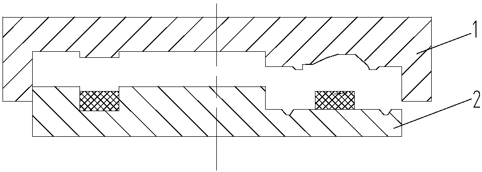
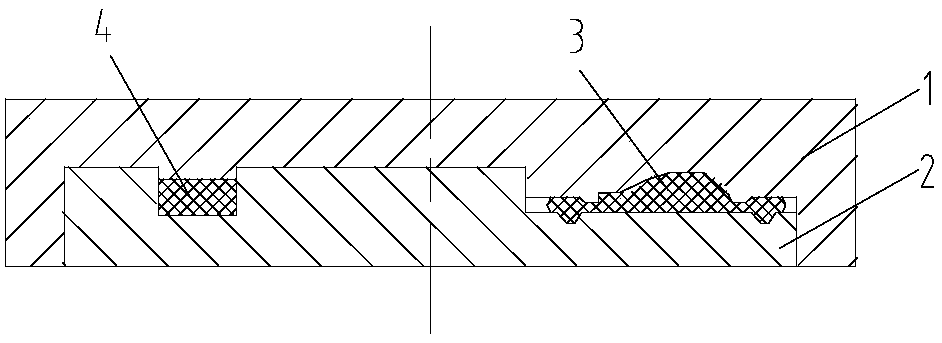
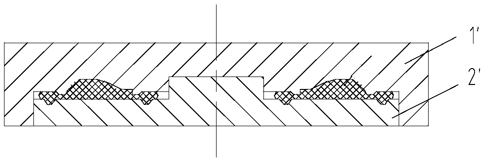
[0031] The disc forging die of the present embodiment is as Figure 1 to Figure 3 As shown, two pairs of molds are included, one of which is as figure 1 , 2 As shown, it consists of a front upper die 1 and a front lower die 2. After the front upper die 1 and the front lower die 2 are closed, the inner cavity is divided into two halves, and the forming part 3 and the The receiving part 4 conforms to the shape of the forging blank. Another pair of molds such as image 3 As shown, it is the finished upper mold 1' and the finished lower mold 2' whose inner cavity matches the shape of the finished forging after mold closing.

[0032] In order to suppress the misalignment force of the mold in the partition forming forging process, and avoid excessive misalignment leading to the scrapping of forgings and the tendency of mold cracking, the mold of this embodiment is provided with a self-locking structure, that is, the front upper mold 1 and the finished upper mold 1' The outer cir...

Embodiment 2

[0041] The disc forging die of the present embodiment is as Figure 8 to Figure 11 As shown, two pairs of dies are also included, one of which is as Figure 8 , 9 As shown, it consists of a front upper die 1 and a front lower die 2. After the front upper die 1 and the front lower die 2 are closed, the inner cavity is divided into two halves, and the forming part 3 and the The receiving part 4 is formed by receiving the shape of the forging blank, and the receiving part includes a detachable mold core installation position located at the front upper die 1 and a detachable core positioning recess 4-1 located at the center of the front lower die 2 . In this way, if Figure 10 , 11 As shown, the finished upper mold and the finished lower mold whose inner cavity matches the shape of the finished forging after mold closing are essentially composed of the front upper mold 1 and the front lower mold 2 embedded with the detachable core 1-1. The detachable mold core 1-1 has a formin...


PUM


Abstract

The invention relates to a disc type forge piece forging mold and a forging method, and belongs to the technical field of metal forging. The mold comprises a finished upper mold and a finished lower mold, wherein the appearance of an inner cavity formed after the finished upper mold and the finished lower mold are closed is matched with that of a finished forge piece; the mold further comprises at least one pair of front upper molds and front lower mold, wherein an inner cavity formed after each front upper mold and the corresponding front lower mold are closed is composed of a molding portion of which the appearance is matched with that of the finished forge piece and a containing portion used for accepting the appearance of a forge piece blank. According to the disc type forge piece forging mold and the forging method, a free forging technology is replaced with a mold forging technology, the forge piece is high in molding precision, part of disc type pieces can adopt a precise mold forging technology, materials are saved, and the material utilization rate is significantly increased; in addition, by adopting a partition molding method, the molding force in the whole molding process is decreased, production of the disc type pieces of the large specification can be completed only by adopting press equipment of small tonnage, the potential of the equipment can be fully excavated, and unnecessary equipment investment and energy consumption are avoided.

Description

technical field [0001] The invention relates to a forging die, in particular to a disc forging die, and also relates to a corresponding forging method, which belongs to the technical field of metal forging. Background technique [0002] Disc parts widely used in various mechanical equipment are often produced by forging. Because the blank is formed in the die, the die forging process has a small forging allowance, and can directly complete the forming of complex sections such as ribs and ribs that do not need to be processed, so it is suitable for producing various forgings with complex shapes. [0003] In practice, the shape of large-scale disk parts is usually relatively simple, and the die forging process is more suitable. However, because of the large outer circle and the large projected area in the forging direction of the forging, the required deformation force is large, and the existing die forging equipment is often used. The tonnage is difficult to meet the forming...

Claims


Application Information

Patent Timeline
Patent Type & Authority Patents(China)
IPC IPC(8): B21J13/02B21J5/02
CPCB21J5/025B21J13/02
Inventor 孙超阮发林
Owner CRRC QISHUYAN INSTITUTE CO LTD
Why Eureka
Try Eureka