
Plasma reaction cavity seepage detection method

A technology of plasma reaction and detection method, which is applied in the field of semiconductor manufacturing, can solve the problems of constant reading value of vacuum pressure gauge and failure to detect leakage, etc., and achieve accurate detection effect

Inactive Publication Date: 2016-07-06
WUHAN XINXIN SEMICON MFG CO LTD
View PDF9 Cites 5 Cited by
  • Summary
  • Abstract
  • Description
  • Claims
  • Application Information

AI Technical Summary

Problems solved by technology

However, it is necessary to ensure that there is no problem with the vacuum pressure gauge during the measurement; if the pressure value of the plasma reaction chamber changes very little before and after a certain period of time, and the accuracy of the vacuum pressure gauge is not enough to distinguish, there will be leakage rate measurement errors; and, during use When there is a leak in the plasma reaction chamber, the leaked substances can be discharged in time through the discharge port of the plasma reaction chamber, resulting in the same reading value of the vacuum pressure gauge before and after, and the leakage cannot be detected

Method used


Image

  • Plasma reaction cavity seepage detection method

Examples


Embodiment Construction

[0024] The principles and features of the present invention are described below in conjunction with the accompanying drawings, and the examples given are only used to explain the present invention, and are not intended to limit the scope of the present invention.

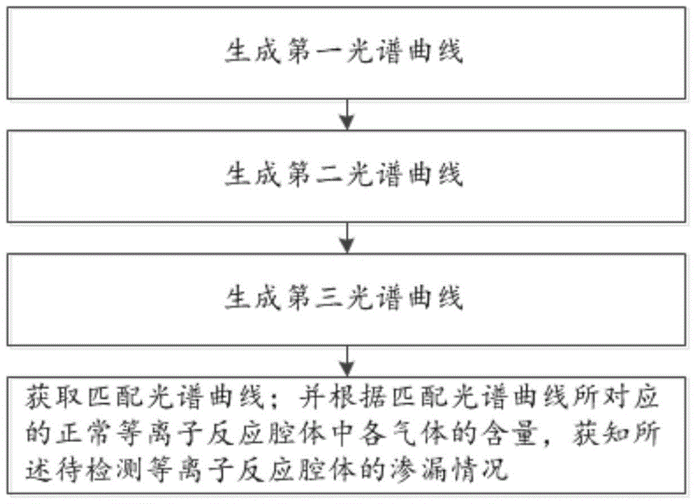
[0025] Such as figure 1 Shown, a kind of leakage detection method of plasma reaction chamber comprises the following steps:

[0026] Step 1: Introduce a predetermined content of fluoroalkyl gas and a known content of fluoroalkyl gas different from the preset content into the normal plasma reaction chamber respectively, insert preset excitation energy to ionize the gas, and respectively collecting spectral lines emitted during the ionization process to generate a first spectral curve;

[0027] Step 2: Introduce the combination gas of the fluoroalkyl gas with the preset content and other gases with different known contents into the normal plasma reaction chamber respectively, connect the preset excitation energy to i...


PUM


Abstract

The invention relates to a plasma reaction cavity seepage detection method. The seepage situation of a plasma reaction cavity under detection is obtained according to the content of each type of gas in a normal plasma reaction cavity corresponding to a matched spectrum curve so that detection is accurate, the causes of seepage of the plasma reaction cavity under detection can be speculated according to the content of each type of gas in the plasma reaction cavity under detection, and thus seepage can be timely eliminated.

Description

technical field [0001] The invention relates to the technical field of semiconductor manufacturing, in particular to a method for detecting leakage of a plasma reaction chamber. Background technique [0002] All plasma reaction chambers used in the semiconductor manufacturing industry need to be tested for leaks to ensure that the plasma reaction chamber is in a stable working environment. The existing leak detection method is to use a vacuum pressure gauge as a measuring tool to measure the pressure value of the plasma reaction chamber before and after a certain period of time, and use the ratio of the difference between the two pressure values ​​before and after the time period as the value of the plasma reaction chamber. leak rate. However, it is necessary to ensure that there is no problem with the vacuum pressure gauge during the measurement; if the pressure value of the plasma reaction chamber changes very little before and after a certain period of time, and the accu...

Claims


Application Information

Patent Timeline
Patent Type & Authority Applications(China)
IPC IPC(8): G01M3/02
CPCG01M3/02
Inventor 任连娟陆飞
Owner WUHAN XINXIN SEMICON MFG CO LTD
Learn More