
A fuel tank refueling pump refueling control method for a power station

A technology of refueling control and fuel tank, which is applied in special dispensing devices, packaging, dispensing devices, etc., to achieve high social and economic benefits, save time, and facilitate refueling

Active Publication Date: 2018-02-16
JIANGXI QINGHUA TAIHAO SANBO ELECTRICAL MACHINE
View PDF9 Cites 0 Cited by
  • Summary
  • Abstract
  • Description
  • Claims
  • Application Information

AI Technical Summary

Problems solved by technology

[0004] The object of the present invention is to provide a fuel tank refueling pump refueling control system in a power station, which solves the problem of electric refueling of the fuel tank in the power station, which is convenient and fast, saves time, manpower and material resources, and realizes uninterrupted operation of the power station The function of fuel supply can be used in the fuel tank of the power station, and can also be extended to other liquid filling devices, with a wide range of applications

Method used


Image

  • A fuel tank refueling pump refueling control method for a power station

Examples


Embodiment Construction

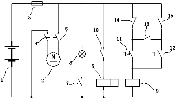
[0012] Such as figure 1 As shown, the control system consists of battery 1, oil pump 2, insurance 3, contact switch a4, contact switch b5, indicator light 6, contact switch c7, contactor 8, relay 9, relay switch a10, manual button switch 11, automatic button Sub-switch 12, relay switch b13, upper liquid level switch 14, lower liquid level switch 15 and so on. The oil pump 2 is connected to the contact switch a4 and the contact switch b5 to form the first circuit branch; the indicator light 6 is connected to the contact switch c7 to form the second circuit branch; the relay switch a10 is connected to the contactor 8 to form the third circuit branch; the relay 9 is connected to the manual The button switch 11 and the automatic button switch 12, the manual button switch 11 is connected to one end of the upper liquid level switch 14 and the relay switch b13, and the automatic button switch 12 is connected to the other end of the lower liquid level switch 15 and the relay switch b1...


PUM


Abstract

The invention relates to a refueling control system and method for a refueling pump of a fuel tank of a power station. Main devices comprise a storage battery, a fuel pump, an upper liquid level switch, a lower liquid level switch, a contactor, a relay, toggle switches, an indicator lamp and a safety part. An automatic refueling manner and a manual refueling manner are set, and two work manners are selected by the toggle switches. When the automatic refueling manner is selected and the liquid level of the fuel tank is on the lower liquid level, the refueling pump starts to work; and when refueling is carried out till the liquid level is on the upper liquid level, the refueling pump stops working. When the manual refueling manner is selected and the liquid level of the fuel tank is lower than the upper liquid level, the refueling pump starts to work; and when refueling is carried out till the liquid level is on the upper liquid level, the refueling pump stops working. According to the refueling control system and method, the problem about electric refueling of the fuel tank of the power station is solved, and the function of ceaseless fuel supply during work of the power station is achieved.

Description

technical field [0001] The invention relates to a fuel tank refueling technology of a power station, in particular to a control system and method for electrically controlling refueling through a fuel pump. Background technique [0002] The high-power power station consumes a lot of fuel, and the fuel tank is equipped with a large volume. Manual refueling is time-consuming, laborious, inconvenient to operate, easy to cause waste, and cannot meet the uninterrupted fuel supply function of the power station. [0003] The invention solves the problem of electric refueling of the fuel tank of the power station, is convenient and quick to refuel, saves time, manpower and material resources, and realizes the function of uninterrupted fuel supply when the power station is working. The utility model is extended to be used in other liquid filling devices, has a wide application range, and has high social and economic benefits. Contents of the invention [0004] The object of the pre...

Claims


Application Information

Patent Timeline
Patent Type & Authority Patents(China)
IPC IPC(8): B67D7/30
CPCB67D7/302
Inventor 蒋继云
Owner JIANGXI QINGHUA TAIHAO SANBO ELECTRICAL MACHINE
Learn More