Mechanical arm

A robotic arm and hand grasping technology, applied in the direction of manipulators, program-controlled manipulators, manufacturing tools, etc., can solve problems such as low safety factor, unfavorable production efficiency, and unstable movements

Inactive Publication Date: 2016-07-06
徐兰曾
View PDF0 Cites 0 Cited by
  • Summary
  • Abstract
  • Description
  • Claims
  • Application Information

AI Technical Summary

Problems solved by technology

Considering the production cost in actual application, the operation of grabbing and transporting products is often completed by some simple electric or pneumatic manipulators. Because the device is relatively simple, although the production cost is reduced to a certain extent, the actual operation does not move. Stable, low safety factor, not only not conducive to the improvement of production efficiency, but also hidden safety hazards

Method used


Image

  • Mechanical arm

Examples


Embodiment Construction

[0016] The technical solutions in the embodiments of the present invention will be clearly and completely described below in conjunction with the accompanying drawings.

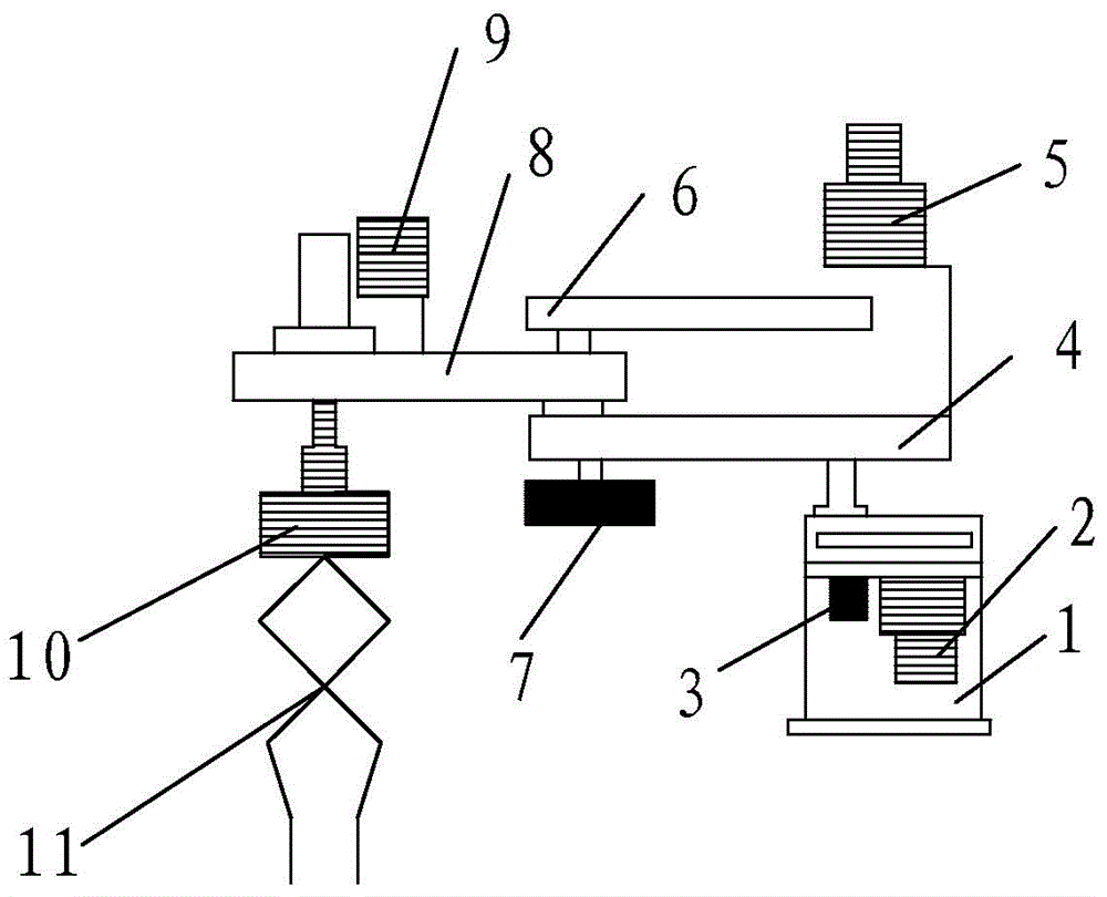
[0017] Such as figure 1 As shown, a mechanical arm includes a fuselage 1 and a rotatable boom 4 arranged thereon; a rotatable forearm 8 is installed above the boom 4; a synchronous belt 6 is installed above one end of the forearm 8, and the other A hand grip 11 is installed below one end.

[0018] Wherein, photoelectric encoder 1 3 and boom motor 2 are arranged below the rotary joint of boom 4; photoelectric encoder 2 7 is arranged below the rotary joint of forearm 8; forearm motor 5 is installed above the synchronous belt 6 end; A wrist lifting motor 9 is arranged above one end of the rotary joint of the forearm 8 ; a hand grip motor 10 is arranged above the hand grip 11 .

[0019] Such as figure 1 As shown, the present invention mainly includes three rotating joints (respectively controlling the rotation...


PUM


Abstract

The invention discloses a mechanical arm which comprises a machine body and a rotatable big arm disposed on the machine body, wherein a rotatable small arm is installed above the big arm; and a synchronous belt is installed above one end of the small arm, and a handle is installed under the other end. The mechanical arm integrates advantages of electric and pneumatic mechanical arms and has the advantages that operations are convenient; accumulate positioning is carried out; stability is high; safe production is ensured; and production efficiency is increased.

Description

technical field [0001] The invention relates to a mechanical arm. Background technique [0002] In the field of machining, manipulators are widely used. Considering the production cost in actual application, the operation of grabbing and transporting products is often completed by some simple electric or pneumatic manipulators. Because the device is relatively simple, although the production cost is reduced to a certain extent, the actual operation does not move. Stable and low safety factor, not only is not conducive to the improvement of production efficiency, but also has potential safety hazards. Contents of the invention [0003] In order to solve the above-mentioned technical problems, the present invention provides a new planar articulated mechanical arm, which combines the advantages of electric and pneumatic manipulators, not only easy to operate, but also capable of precise positioning and high stability, which is beneficial to safe production and improves prod...

Claims


Application Information

Patent Timeline
IPC IPC(8): B25J9/04B25J9/18
Inventor 徐兰曾
Owner 徐兰曾
Why Eureka
Try Eureka