Eureka AIR delivers breakthrough ideas for toughest innovation challenges, trusted by R&D personnel around the world.

A General Group Delay Ripple Automated Test Method

An automated test and group delay technology, applied in transmission monitoring, radio transmission systems, electrical components, etc., can solve problems such as increasing bit error rate, signal phase distortion, reducing signal-to-noise ratio, etc., to eliminate local fluctuations, reduce The effect of test error

Active Publication Date: 2018-03-09
CHINA ACADEMY OF SPACE TECHNOLOGY
View PDF1 Cites 0 Cited by
  • Summary
  • Abstract
  • Description
  • Claims
  • Application Information

AI Technical Summary

Problems solved by technology

Once the group delay ripple characteristics of the system are not good, it will cause signal phase distortion, reduce the signal-to-noise ratio, and increase the bit error rate
[0004] The traditional communication satellite transponder channel group delay characteristic test uses the modulator to modulate the signal, after being forwarded by the satellite transponder and then demodulated by the demodulator, it is sent to the frequency discriminator for comparison with the reference signal, so as to obtain the group delay characteristic data, but did not analyze the fluctuations and ups and downs of the group delay curve data, so it is impossible to deeply understand the group delay ripple characteristics of the satellite transponder channel, so that it is impossible to fully understand the impact of the satellite transponder channel on the quality of the transmitted signal

Method used

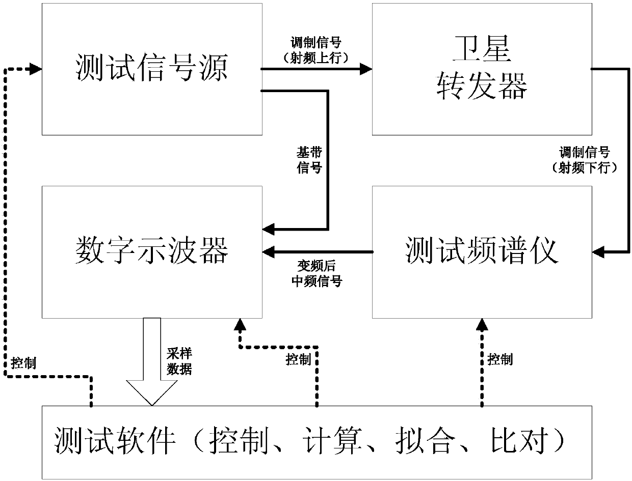

Image

  • A General Group Delay Ripple Automated Test Method
  • A General Group Delay Ripple Automated Test Method
  • A General Group Delay Ripple Automated Test Method

Examples


Embodiment

[0031] Taking a satellite transponder as an example, the uplink center frequency is 12700MHz, the downlink center frequency is 10700MHz, and the bandwidth is 48MHz. Follow the steps below:

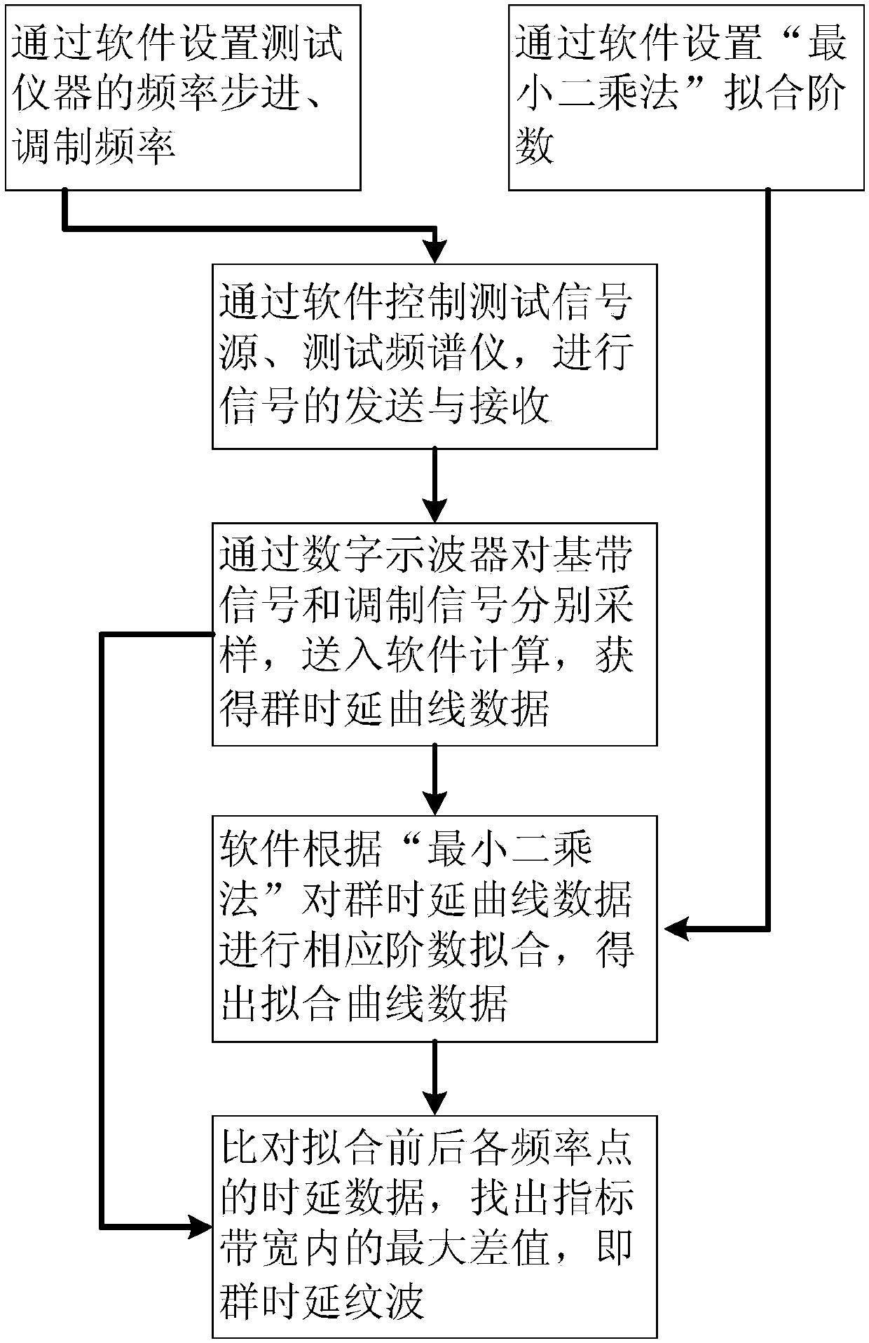
[0032] 1. According to the requirements of the document, the test group delay characteristics need to be extended by 4MHz on the left and right, that is, the test bandwidth becomes 56MHz, and the frequency step is set to 2MHz through the test software, that is, the number of test points is 29, and the modulation frequency is 0.4MHz. Multiplication" fitting order is 6th order.

[0033] 2. According to the software setting, the signal source generates one baseband signal (modulation frequency is 0.4MHz) and sends it directly to the digital oscilloscope, and the other one is an uplink modulation signal (carrier is 12700MHz, modulation frequency is 0.4MHz) and sends it to the satellite, which is transmitted by the satellite The downlink modulation signal (the carrier is 10700MHz, the modulatio...


PUM


Abstract

The invention relates to an automatic test method for general group delay ripple. A test signal source generates two paths of baseband signals, one path of baseband signal is sent to a digital oscilloscope to be directly sampled as a reference, the other path of baseband signal is used for frequency modulation on a high-frequency carrier, the frequency modulation wave is changed to intermediate frequency from variable frequency by a test spectrometer after passing through a satellite transponder and then is sampled by the digital oscilloscope to obtain group delay curve data to be tested in a frequency range; the obtained group delay curve data is fitted according to a least square method to obtain fitting curve data reflecting overall trend; and the two groups of curve data before and after fitting are compared, and the maximum difference value in an index frequency range is found out, namely group delay ripple. According to the method, the curve is fitted by the least square method, an approximate curve is taken from the minimum angle of total deviation, a rule is found out from a large number of given data, a curve is constructed to reflect the general trend of data points, the local fluctuation of the curve is eliminated, and thus, the group delay ripple reflecting global characteristic is obtained.

Description

technical field [0001] The invention is suitable for the field of spacecraft ground testing, especially for automatic testing of communication satellite transponder group delay ripple, and belongs to the technical field of radio frequency testing. Background technique [0002] Group delay is an important parameter to describe the phase-frequency characteristics of a transmission system. Group delay ripple describes the fluctuation and fluctuation of group delay, and is an important indicator to measure the phase linearity of a continuous signal passing through a transmission system. [0003] Group delay ripple not only determines the fluctuation of signal transmission delay generated by the system, but also is closely related to signal transmission distortion and has a great impact on signal transmission quality. It is a major technical indicator of the current satellite communication system. Once the group delay ripple characteristics of the system are not good, it will cau...

Claims


Application Information

Patent Timeline
Patent Type & Authority Patents(China)
IPC IPC(8): H04B17/364H04B7/185
CPCH04B7/18515H04B17/364H04B7/18519
Inventor 索洪海马强钟良玉徐汝军吴越
Owner CHINA ACADEMY OF SPACE TECHNOLOGY
Why Eureka
Eureka Blog
Learn More