Eureka AIR delivers breakthrough ideas for toughest innovation challenges, trusted by R&D personnel around the world.

Double-sided backlight source and double-sided display device

A double-sided display device, backlight technology, applied in optics, nonlinear optics, instruments, etc., can solve the problems of increased energy consumption, thicker thickness, and high noise, and achieve increased energy consumption and noise, and the whole machine is light and thin. Effect

Inactive Publication Date: 2016-06-29
HISENSE VISUAL TECH CO LTD
View PDF4 Cites 9 Cited by
  • Summary
  • Abstract
  • Description
  • Claims
  • Application Information

AI Technical Summary

Problems solved by technology

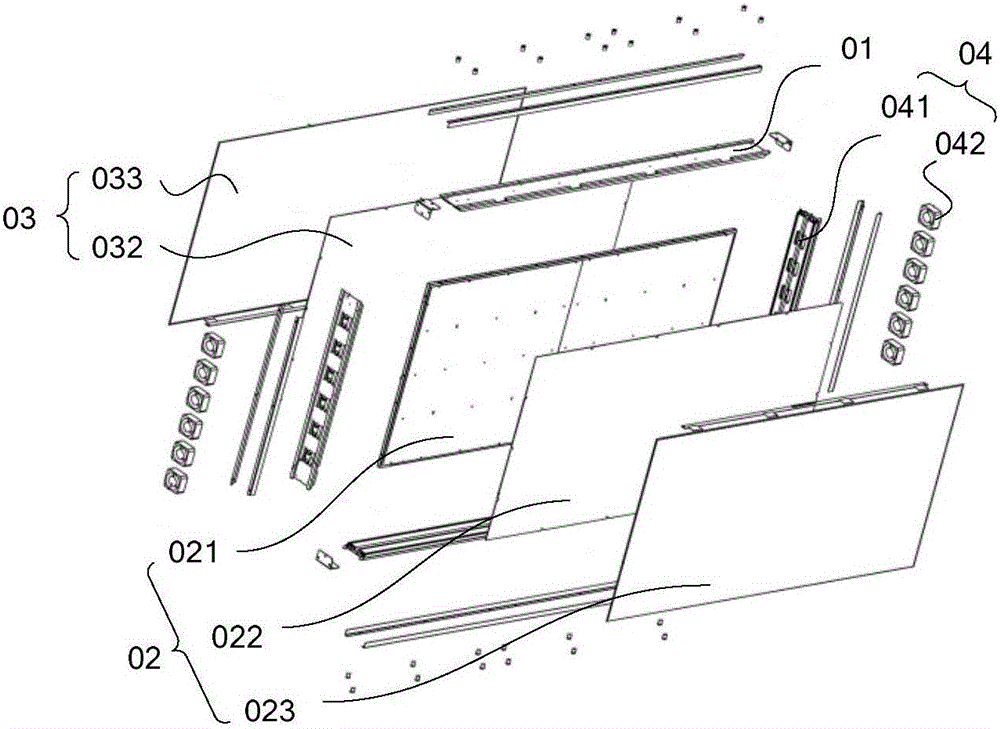
[0004] However, the technical solution of the prior art has the following disadvantages: the heat dissipation mainly adopts multiple fans 042 to forcibly dissipate heat, so the noise is relatively large, and energy consumption increases; due to the large volume of the fans, the thickness of the whole machine is relatively thick

Method used


Image

  • Double-sided backlight source and double-sided display device
  • Double-sided backlight source and double-sided display device
  • Double-sided backlight source and double-sided display device

Examples


Embodiment 1

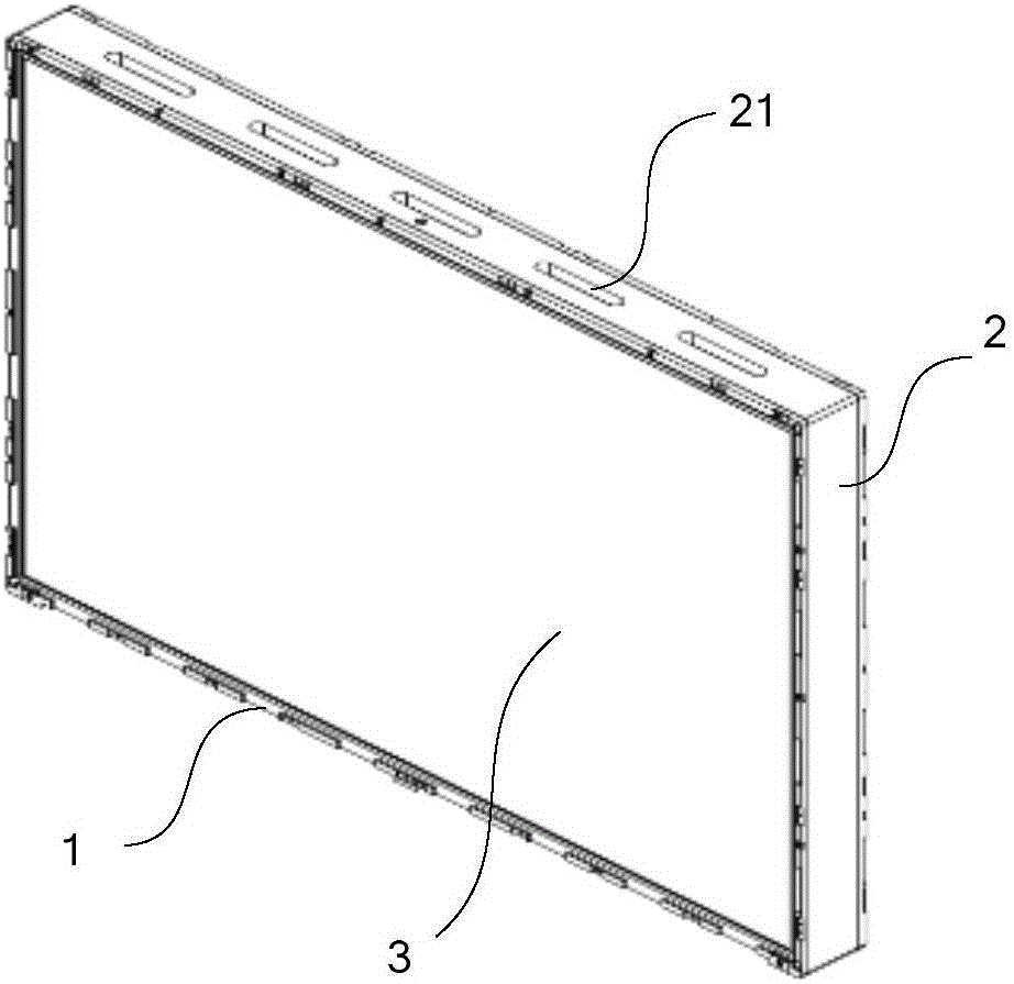
[0030] Such as Figure 4 and Figure 5 As shown, the backlight module 3 is a direct-type backlight module, and the light source 31 includes a heat sink 311 made of heat-conducting material and a first lamp board 312 and a second lamp board 313 arranged on both sides of the heat sink 311. Point light sources are distributed on the lamp board 312 and the second lamp board 313 , and the position of the ventilation hole 21 corresponds to that of the heat sink 311 . Such as Figure 5 As shown, the first lamp board 312 and the second lamp board 313 are distributed with point light sources, which are arranged on both sides of the cooling frame 311, which can respectively provide light sources for both sides of the cooling frame. A large amount of heat generated by the point light sources on the first lamp board 312 and the second lamp board 313 is dissipated through conduction and radiation, and then the heat is dissipated through the heat dissipation channel.

[0031] It should b...

Embodiment 2

[0037] Such as Figure 7 As shown, the backlight module 3 of this embodiment is a side-type backlight module, the light source 31 includes a light bar 311 ′, and the ventilation hole 21 (not shown in the figure) corresponds to the position of the light bar 311 ′. When the backlight module 3 is a side-entry type, its heat mainly comes from the light bar 311'. Therefore, in order to effectively dissipate heat from the backlight module 3, the position of the ventilation hole 21 corresponds to the position of the light bar 311', so that the light bar is in a heat dissipation position. channel.

[0038] Specifically, in order to enable the light source 31 to provide backlight for double-sided display, such as Figure 7 As shown, the backlight module 3 includes a first light guide plate 32' and a second light guide plate 33', the light incident surfaces of the first light guide plate 32' and the second light guide plate 33' are opposite to the light bar 311', The light emitting su...


PUM


Abstract

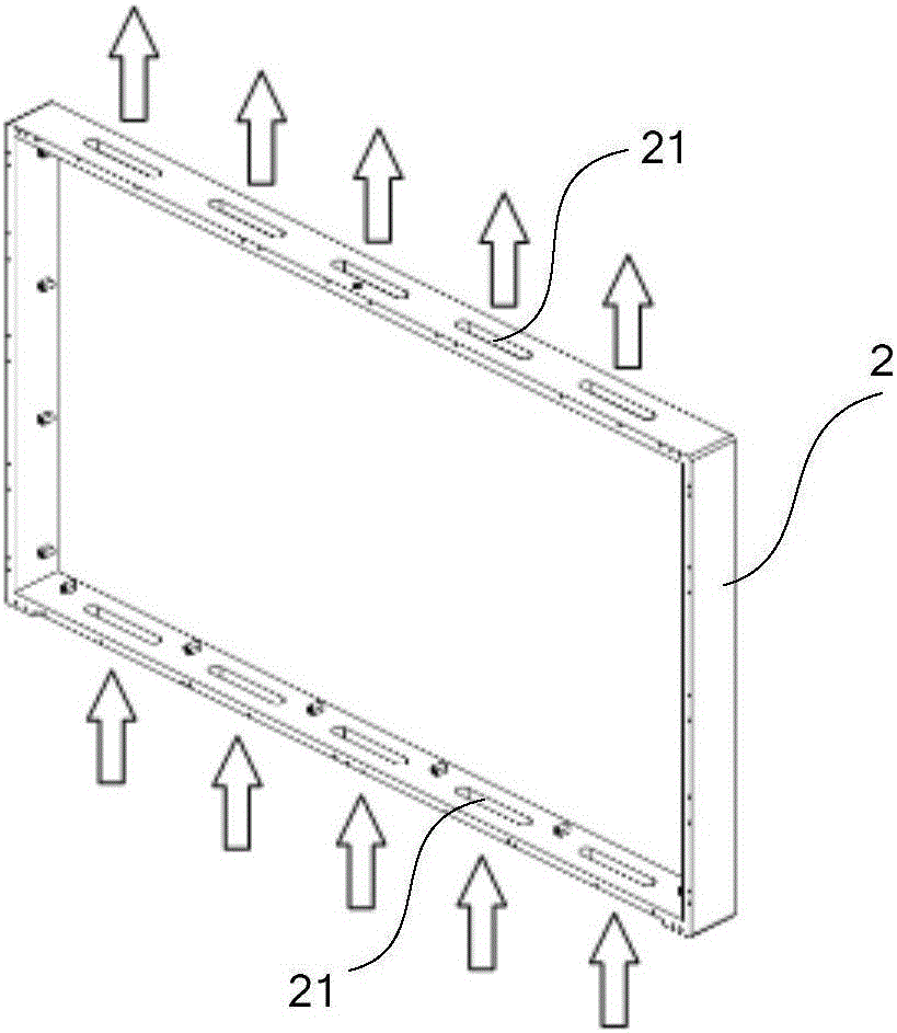
The invention discloses a double-sided backlight source and a double-sided display device and relates to the technical field of display. Under the condition that the double-sided display device dissipates heat normally, energy consumption and noises are not increased and the whole machine is relatively light. The double-sided backlight source can provide double-sided backlight for the double-sided display device, and comprises an outer frame and a backlight module arranged in the outer frame, wherein the backlight module comprises a light emitting source; and vent holes are formed in the parts, corresponding to the light emitting source, of upper and lower edge frames of the outer frame, so that a heat dissipation channel for forming natural air convection is formed in the outer frame. The double-sided backlight source is used for realizing heat dissipation of the double-sided display device.

Description

technical field [0001] The invention relates to the field of display technology, in particular to a double-sided backlight source and a double-sided display device. Background technique [0002] At present, the use of display devices has been basically popularized and has become an indispensable part of people's lives. The general display devices are displayed on one side and then installed on the wall, which meets the general needs. However, in some crowded public places such as stations, airports, and exhibition centers, the display devices with single-sided display cannot satisfy the audience well. Viewing required. [0003] The prior art provides a double-sided display module, such as figure 1 As shown, it includes an installation frame 01, and a first display module 02 and a second display module 03 fixed on the front and back of the installation frame 01 to realize double-sided display of the display device. Such as figure 1 As shown, the first display module 02 in...

Claims


Application Information

Patent Timeline
IPC IPC(8): G02F1/13357
CPCG02F1/133602G02F1/133605G02F1/133606G02F1/133615G02F1/133607G02F1/133628
Inventor 田五林
Owner HISENSE VISUAL TECH CO LTD
Why Eureka
Eureka Blog
Learn More