A measuring device for mid-infrared blazed grating diffraction efficiency

A diffraction efficiency and measurement device technology, applied in the direction of testing optical performance, etc., can solve problems such as center wavelength drift and inaccurate measurement results, and achieve the effect of reducing measurement errors, complete measurement results, and intuitive results

Active Publication Date: 2017-12-15
DALIAN INST OF CHEM PHYSICS CHINESE ACAD OF SCI
View PDF5 Cites 0 Cited by
  • Summary
  • Abstract
  • Description
  • Claims
  • Application Information

AI Technical Summary

Problems solved by technology

In addition, because the center wavelength of the test light source will drift with time and changes in the external environment, this will also cause inaccurate measurement results.

Method used


Image

  • A measuring device for mid-infrared blazed grating diffraction efficiency

Examples


Embodiment Construction

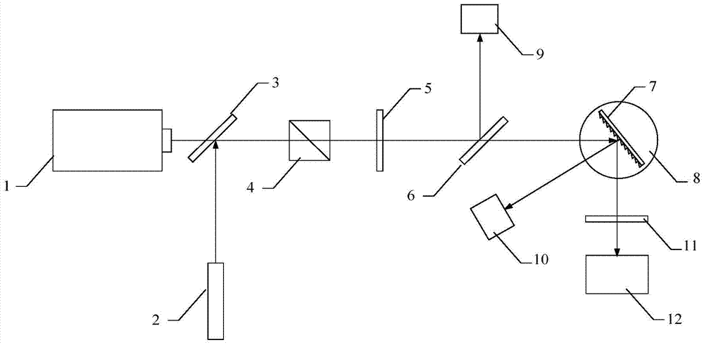
[0023] as attached figure 1 As shown, a measuring device for the diffraction efficiency of a mid-infrared grating is characterized in that the device includes: a tunable mid-infrared laser 1 and a guiding laser 2, and the light emitted by the tunable mid-infrared laser 1 and the guiding laser 2 is respectively irradiated to On both sides of the beam combiner 3, the light combined by the beam combiner 3 passes through the polarizer 4 and the half-wave plate 5 in turn, and then irradiates the polarization beam splitter 6, and the light passing through the polarization beam splitter 6 is divided into two paths, and one path of light enters the The first power meter 9 , the other path of light is diffracted by the grating 7 to be measured and divided into two paths again, one path of diffracted light is input into the spectrometer 12 through the attenuation plate 11 , and the other path of diffracted light enters the second power meter 10 .

[0024] When measuring the first-order ...


PUM


Abstract

A measuring device for the diffraction efficiency of a mid-infrared grating, which includes a tunable mid-infrared test laser, a guiding laser, a polarizing device, a polarization splitting device, a grating to be measured, a three-dimensional electric displacement stage, a photodetector, an attenuation sheet, and a spectrometer. The mid-infrared grating is used to directly measure the diffraction efficiency of the mid-infrared grating with different wavelengths, different incident angles, and different polarization characteristics of the first-order diffraction output power of the mid-infrared grating, which more truly reflects the practical application of the mid-infrared grating. The actual diffraction efficiency of . The measurement accuracy is guaranteed by using polarization spectroscopic measurement and dual optical path dual detector comparison detection. The continuous measurement of the first-order spectral diffraction efficiency of the grating in the mid-infrared band can be realized.

Description

technical field [0001] The invention relates to grating diffraction efficiency, in particular to a measuring device for mid-infrared grating diffraction efficiency. Background technique [0002] Lasers in the mid-infrared band have important applications in the fields of photoelectric countermeasures, laser remote sensing, laser detection, and component analysis. Certain mid-infrared lasers such as HF / DF lasers, CO lasers, CO 2 Lasers and the like oscillate simultaneously at multiple wavelengths. In actual work, in order to obtain laser output at a specific wavelength, a wavelength-selective resonator must be used. Usually this kind of resonant cavity often includes a wavelength selector, and the mid-infrared diffraction grating concentrates the light energy to the -1 order spectrum, which is a good wavelength selector. The first-order diffraction efficiency of the mid-infrared grating directly determines the loss of the laser resonator, so the measurement of the diffract...

Claims


Application Information

Patent Timeline
Patent Type & Authority Patents(China)
IPC IPC(8): G01M11/02
Inventor 王元虎多丽萍金玉奇唐书凯李国富于海军李留成汪健曹靖康元福
Owner DALIAN INST OF CHEM PHYSICS CHINESE ACAD OF SCI
Why Eureka
Try Eureka