
Oil quantity detection device for oil disc of sewing machine and sewing machine

A detection device and sewing machine technology, which is applied to sewing machine components, sewing equipment, lubrication/cooling devices, etc., can solve problems such as excessive refueling, neglect, and oil leakage, so as to improve detection accuracy and avoid oil leakage , The effect of consistent motion trajectory

Active Publication Date: 2016-06-29
JACK SEWING MASCH CO LTD
View PDF9 Cites 7 Cited by
  • Summary
  • Abstract
  • Description
  • Claims
  • Application Information

AI Technical Summary

Problems solved by technology

Therefore, the above-mentioned oil quantity detection device can detect the information of the low level of oil in the oil box and send out an alarm, but it ignores the detection of the information of the high level of oil in the oil box, resulting in the phenomenon of excessive oiling, which in turn causes the sewing machine to roll over Occasional oil leakage, causing a series of unnecessary troubles

Method used


Image

  • Oil quantity detection device for oil disc of sewing machine and sewing machine
  • Oil quantity detection device for oil disc of sewing machine and sewing machine
  • Oil quantity detection device for oil disc of sewing machine and sewing machine

Examples


Embodiment 1

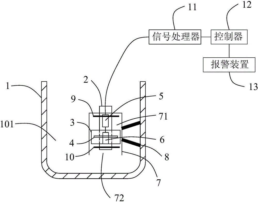
[0057] Embodiment one, as figure 1 As shown, the casing 7 only includes an inverted U-shaped casing body 73, the interior of the casing body 73 forms the inner chamber 71, the opening at the lower end of the casing body 73 forms the oil through hole 72, and the casing body 73 The lower end of the lower end of the oil pan 1 is not in contact with the lower end surface of the oil pan 1 , and the space formed between the two allows the oil to flow into the inner cavity 71 from the oil through hole 72 . The side of the casing body 73 is fixedly connected with the oil pan 1 through at least one fixed connecting rod 8, the fixed connecting rod 8 and the casing 7, the fixed connecting rod 8 and the oil pan 1 can be fixed by screws or welded. . Part of the pillar 2 on which the high sensor 5 and the low sensor 6 are installed is also accommodated in the inner cavity 71 of the casing 7, and the float 3 is sleeved on the pillar 2 and slides up and down along the pillar 2, so the suppor...

Embodiment 2

[0058] Embodiment two, such as Figure 5 As shown, the casing 7 includes an inverted U-shaped casing body 73 and a connecting portion 74 extending straight outward from the lower end of the casing body 73, and the oil hole 72 is opened in the casing body 73 (that is, the casing 7), the connecting portion 74 is welded and fixed to the lower end surface of the oil pan 1 or fixed by fasteners, so that the casing 7 and the oil pan 1 are fixedly connected. The pillar 2 on which the high sensor 5 and the low sensor 6 are installed is also accommodated in the inner chamber 71 of the casing 7, and the float 3 is sleeved on the pillar 2 and slides up and down along the pillar 2, so the pillar 2 is opposite to the up and down of the float 3. The floating plays a guiding role, thereby effectively improving the stability of the float 3 floating up and down, thereby improving the detection accuracy of the oil quantity detection. At the same time, the lower end surface of the pillar 2 and ...

Embodiment 3

[0059] Embodiment three, as Image 6 As shown, the casing 7 includes an inverted U-shaped casing body 73 and a connecting portion 74 extending straight outward from the lower end of the casing body 73, and the oil hole 72 is opened in the casing body 73 (that is, the casing 7), the connecting portion 74 is welded and fixed to the lower end surface of the oil pan 1 or fixed by fasteners, so that the casing 7 and the oil pan 1 are fixedly connected. The pillar 2 on which the high position sensor 5 and the low position sensor 6 are installed is located outside the housing body 73 , and the lower end surface of the pillar 2 is welded or riveted or screwed to the upper end surface of the connecting portion 74 . The signal lines used to connect the high level sensor 5 and the signal processor 11, and the low level sensor 6 and the signal processor 11 go out from the lower end of the oil pan 1 downward, and are routed from the outside of the oil pan 1, so that it is convenient to do ...


PUM


Abstract

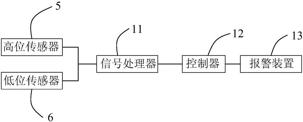
The invention provides an oil quantity detection device for an oil disc of a sewing machine. The oil quantity detection device comprises the oil disc provided with an oil cavity, and further comprises a support which is fixedly arranged in the oil cavity, a floater which is located in the oil cavity and can float up and down along the height change of an oil level in the oil cavity, and an element to be induced, which is fixedly arranged on the floater, wherein the support is internally provided with a sealing cavity; and the sealing cavity is internally and fixedly provided with sensors for inducing the element to be induced. According to the oil quantity detection device, the sensors are arranged at the positions with different heights in the oil cavity of the oil disc, so that when the floater drives the element to be induced to float up and down along the height change of the oil level of lubricating oil in the oil cavity, the sensors can induce the element to be induced, and furthermore, high-level oil quantity information or low-level oil quantity information in the oil disc is detected; and a maximum value and a minimum value of the oil quantity in the oil disc can be measured at the same time, so that a phenomenon that the oil quantity in the oil disc is excessive or too less is prevented, the normal work of the sewing machine can be guaranteed, and oil is prevented from leaking when the sewing machine turns on one side.

Description

technical field [0001] The invention relates to an industrial sewing machine, in particular to a device for detecting the amount of oil in the oil pan of the sewing machine and the sewing machine. Background technique [0002] Industrial sewing machines mainly include lockstitch sewing machines, overlock sewing machines, interlock sewing machines, chain sewing machines, etc. Sewing machines mainly rely on mechanical transmission parts for transmission. Therefore, mechanical transmission parts need to be lubricated to prevent wear and aging of sewing machine mechanical transmission parts. At present, the lubricating mechanism of the sewing machine is mainly composed of an oil pan, an oil pump, and an oil pipeline or oil line arranged in the mechanical transmission parts. Disc lubricating oil, and lubricating oil through the oil pipeline, or oil line, or directly sprayed to the rest of the mechanical transmission parts. In addition, with the continuous development of sewing m...

Claims


Application Information

Patent Timeline
Patent Type & Authority Applications(China)
IPC IPC(8): D05B71/00
CPCD05B71/00D05D2205/12
Inventor 王波潘建国万义明
Owner JACK SEWING MASCH CO LTD
Learn More