Al technical title is built by PatSnap Al team. It summarizes the technical point description of the patent document.
A ligation device and suction tube technology, applied in medical science, surgery, etc., can solve problems such as difficulty in seeing the opening of the negative pressure connector, failure to meet medical requirements for disinfection, inconvenience in replacing the suction tube, and pushing the tube, etc. Achieve the effect of reducing medical costs, realizing cleaning and disinfection operations, and significant beneficial effects
Active Publication Date: 2018-03-30
李洪湘
View PDF12 Cites 0 Cited by
Summary
Abstract
Description
Claims
Application Information
AI Technical Summary
This helps you quickly interpret patents by identifying the three key elements:
Problems solved by technology
Method used
Benefits of technology
Problems solved by technology
But the ligation syringe of this structure is extremely inconvenient in the process of replacing the suction tube and the push tube. Since the pushing block and the suction negative pressure connector are all located in the housing, the light in the housing is insufficient, and it is difficult for the user to see the suction tube clearly. The opening on the negative pressure connector makes it very inconvenient to replace the suction tube and push tube
[0004] In order to prevent human tissue fluid from being sucked into the negative pressure pump during the negative pressure suction process, a storage device needs to be installed between the negative pressure pump and the suction pipe. In the patent document of "Ligation Therapy Device", in order to prevent the inflow of tissue fluid, a first liquid storage tank and a spare liquid storage tank are arranged between the suction negative pressure pump and the suction pipe. Due to the use of two liquid storage tanks, it is clear It is very inconvenient, and even does not meet the disinfection effect required by medical treatment, so it is not suitable for repeated use
Method used
Image
Click on the blue label to locate the original text in one second.
Reading with bidirectional positioning of images and text.
Examples
Embodiment Construction
[0025] The present invention will be further described below in conjunction with the accompanying drawings and embodiments.
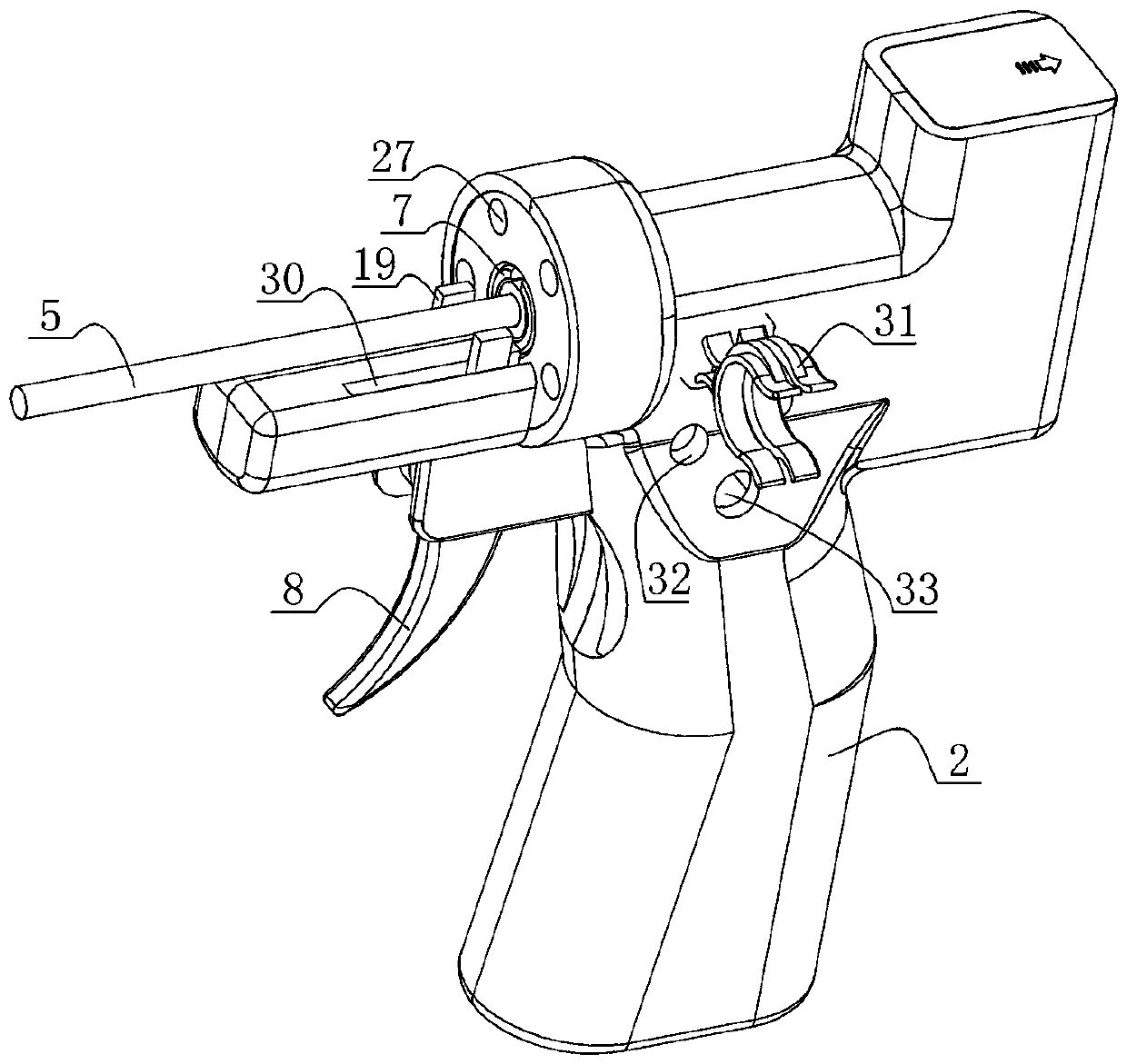
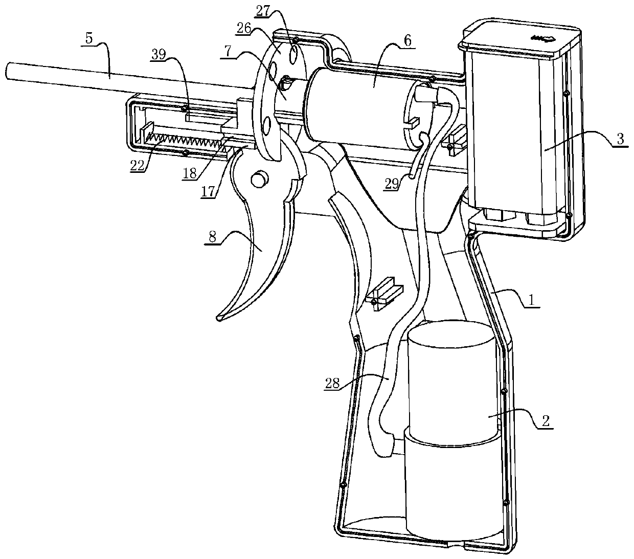
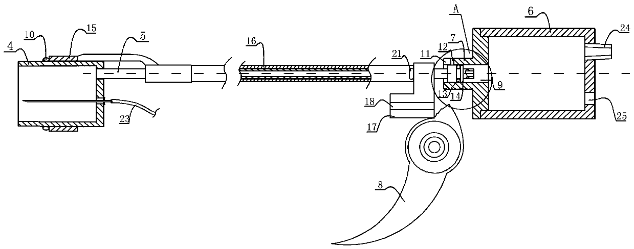
[0026] Such as figure 1 and figure 2 As shown, a perspective view and a sectional view of the reusable ligation device of the present invention are provided, image 3 A schematic structural diagram of the cooperation between the suction tube and the connecting body, the push rod and the push block is given. The shown ligation device includes a housing 1, a negative pressure pump 2, a battery 3, a suction cup 4, a suction tube 5, a storage tank 6, a connection Body 7, trigger 8, push ring 15, push rod 16, push block 17, compression spring 22, housing 1 plays a role of fixing and supporting, negative pressure pump 2, storage battery 3, storage tank 6 and push block 17 are all arranged on In the inner cavity of the casing 1, the battery 3 provides electric energy for the operation of the whole ligation device, and the negative pressure pump 2 is used fo...
PUM
Abstract
The invention provides a loop ligature device capable of being repeatedly used. The loop ligature device comprises a shell, a negative pressure suction pump, a storage battery, a sucker, a straw, a push ring, a push rod, a storage tank and a trigger, wherein the front end of the storage tank is provided with a connector, the front end of the straw is communicated with the sucker, and the rear end of the straw is detachably inserted into a cylinder-shaped cavity, so that the straw is communicated with the storage tank. The loop ligature device is characterized in that an opening of the cylinder-shaped cavity on the connector is exposed to the outside, so that a user can replace the straw and the push rod conveniently, and the repeated use of the loop ligature device is realized. According to the loop ligature device provided by the invention, the connector connected with the straw is exposed to the outside, and a push block for driving the push rod is exposed to the outside, so that the straw and the push rod can be conveniently assembled and disassembled, the defect that the connector and the push block can not be seen clearly if being arranged inside the shell is overcome, further, the medical workers can conveniently use the loop ligature device, the medical cost is reduced, the materials are saved, the environment-protecting and energy-saving effects are good, the beneficial effects are obvious, and thus the application and promotion are easy.
Description
technical field [0001] The invention relates to a reusable ligation device, in particular to a reusable ligation device which is convenient for medical personnel to replace suction pipes and push rods. Background technique [0002] In the process of treating patients' hemorrhoids and polyps, rubber rings are usually used to ligate and inject drugs into the ligated tissues, so that the ligated tissues are separated from the human body under the action of the drugs to achieve the purpose of treatment and rehabilitation. Under the requirements of low cost and low consumption of medical appliances, it is undoubtedly a waste to use a set of treatment appliances for a patient in the past, which is not conducive to reducing the burden of seeing a doctor, but also causes waste of labor and materials. The ligature is a trend. [0003] For example, the patent document with the patent number CN201410595665.1 and the invention name "Combined Electric Banding Syringe" discloses a reusab...
Claims
Application Information
Patent Timeline
Application Date:The date an application was filed.
Publication Date:The date a patent or application was officially published.
First Publication Date:The earliest publication date of a patent with the same application number.
Issue Date:Publication date of the patent grant document.
PCT Entry Date:The Entry date of PCT National Phase.
Estimated Expiry Date:The statutory expiry date of a patent right according to the Patent Law, and it is the longest term of protection that the patent right can achieve without the termination of the patent right due to other reasons(Term extension factor has been taken into account ).
Invalid Date:Actual expiry date is based on effective date or publication date of legal transaction data of invalid patent.