
Heat-conducting battery box

A battery box and heat-conducting adhesive technology, which is applied in the use/maintenance of primary batteries, secondary batteries, battery pack components, etc., can solve the problems of poor thermal conductivity and easy dust falling, so as to increase the ability to resist external shocks and Heat dissipation effect, effect of increasing contact area

Active Publication Date: 2016-06-22
NORTHERN ALTAIR NANOTECH CO LTD +2
View PDF4 Cites 17 Cited by
  • Summary
  • Abstract
  • Description
  • Claims
  • Application Information

AI Technical Summary

Problems solved by technology

[0005] The purpose of the present invention is to provide a thermally conductive battery box to solve the technical problems of poor thermal conductivity and easy dust falling in the prior art

Method used


Image

  • Heat-conducting battery box
  • Heat-conducting battery box
  • Heat-conducting battery box

Examples


Embodiment 1

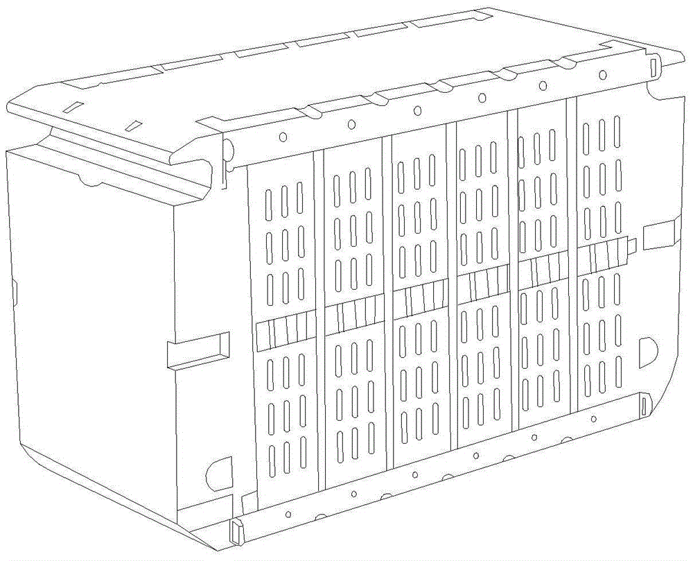
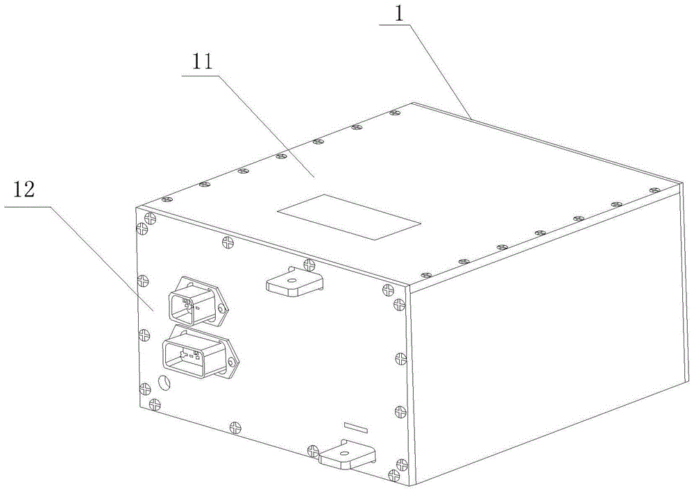
[0043] image 3 Schematic diagram of the structure of the thermally conductive battery box provided by the embodiment of the present invention; Figure 4 based on image 3 Schematic diagram of the structure of the bottom panel of the thermally conductive battery box shown; Figure 5 based on image 3 The schematic diagram of the internal structure of the thermally conductive battery box shown; Image 6 based on image 3 The schematic diagram of the structure of the heat conducting plate of the heat conducting battery box shown; Figure 7 based on Figure 5 A partial enlarged view of the thermally conductive battery box shown; Figure 3-7 As shown, the heat-conducting battery box provided in this embodiment includes a battery box body 1, a plurality of rows of heat-conducting plates 2 are arranged inside the battery box body 1, and batteries 5 are arranged on the heat-conducting plates 2. One, can make the both sides of electric core 5 be close to heat conduction plate 2...

Embodiment 2

[0059] The heat-conducting battery box provided in this embodiment includes a battery box body 1, a plurality of rows of heat-conducting plates 2 are arranged inside the battery box body 1, and batteries 5 are arranged on the heat-conducting plates 2. Since there are multiple heat-conducting plates 2 and batteries 5, it can be Make both sides of the battery cell 5 close to the heat conducting plate 2, so as to improve the heat dissipation efficiency of the battery cell 5;

[0060] The battery box body 1 is a fully enclosed box, which effectively prevents the entry of dust and other fine particles in the air, and also increases the box's ability to resist external shocks; at the same time, all the gaps in the battery box body 1 are filled with heat-conducting glue, so that The heat generated by the battery is dissipated in the fastest way;

[0061] The heat conduction plate 2 includes a separator 21 and a bottom plate 22. The bottom plate 22 is vertically arranged with the sepa...


PUM

PropertyMeasurementUnit
Thermal conductivityaaaaaaaaaa

Abstract

The invention relates to the technical field of battery boxes, in particular to a heat-conducting battery box. The heat-conducting battery box comprises a battery box body, wherein multiple rows of heat-conducting plates are arranged in the battery box body and are provided with battery cells; and the battery box body is a totally enclosed box body, so that fine particles, such as dust and the like in air are effectively prevented from entering; and the external attack resistance of the box body is also improved. Meanwhile, all gaps of the battery box body are fully filled with heat-conducting glue, so that the heat generated by a battery is emitted in the fastest manner. Each heat-conducting plate comprises a partition plate and a bottom plate; and each bottom plate is arranged vertically to the corresponding partition plate and is bonded with the bottom part of the battery box body through the heat-conducting glue. Through the arranged bottom plates, the contact area of the heat-conducting plates and the bottom part of the battery box body can be increased; the heat dissipation effect is improved; and the technical problems that the battery box in the prior art is poor in heat-conducting property and dust easily falls into the battery box are solved.

Description

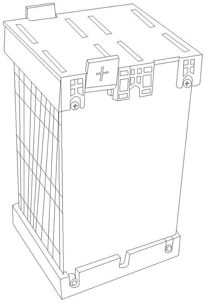
technical field [0001] The invention relates to the technical field of battery boxes, in particular to a heat-conducting battery box. Background technique [0002] The battery will generate a lot of heat during operation. If the heat generated cannot be dissipated in time, there is a risk of explosion. Therefore, the battery box has a good heat dissipation system, which is directly related to the safety of the battery. There are three main ways to dissipate heat, namely heat conduction, heat convection, and heat radiation. At present, the heat dissipation of existing batteries is mainly carried out by heat convection. There are two design methods. The first is that the battery is directly exposed to the air and relies on air convection to dissipate heat. The second is to place the battery in a lot of In the case of the grid, install the fan outside the case. [0003] Such as figure 1 As shown, the cells of the first heat dissipation method are directly exposed to the air,...

Claims


Application Information

Patent Timeline
IPC IPC(8): H01M2/10H01M6/50H01M10/613H01M10/647H01M10/653H01M10/6554H01M10/6555H01M50/20H01M50/24
CPCH01M6/5011H01M6/5038H01M10/613H01M10/647H01M10/653H01M10/6554H01M10/6555H01M50/20H01M50/24Y02E60/10
Inventor 宿斌董文琦马步云史学伟申力方
Owner NORTHERN ALTAIR NANOTECH CO LTD
Learn More