
Novel multifunctional descent control device with cyclic lifting function

A descending device and multi-functional technology, applied in the field of escape devices, can solve problems such as difficult evacuation of personnel, rapid fire spread, and difficulty in fire fighting

Active Publication Date: 2016-06-22
张文革
View PDF10 Cites 3 Cited by
  • Summary
  • Abstract
  • Description
  • Claims
  • Application Information

AI Technical Summary

Problems solved by technology

[0002] With the rapid development of the construction industry, high-rise buildings have sprung up like bamboo shoots after a spring rain, which has brought many problems. For example, once a fire breaks out in a high-rise building, the fire spreads quickly, it is difficult to fight the fire, it is difficult to evacuate people, and it is difficult to escape from a high-rise building. It is a self-rescue method when a fire occurs. Due to the thick smoke and fire, it is difficult for people to escape normally from the stairs and elevators. Surrounded by thick smoke, poisonous gas and flames, many people were buried in the sea of ​​fire. How to escape has become an urgent problem to be solved. The invention of the descending device can enable people in danger to escape accurately on high buildings, but the traditional descending device is too large and cumbersome to operate, delaying the escape time and adding safety hazards to the escape

Method used


Image

  • Novel multifunctional descent control device with cyclic lifting function
  • Novel multifunctional descent control device with cyclic lifting function
  • Novel multifunctional descent control device with cyclic lifting function

Examples


Embodiment Construction

[0022] The present invention will be described in further detail below in conjunction with the accompanying drawings and specific embodiments.

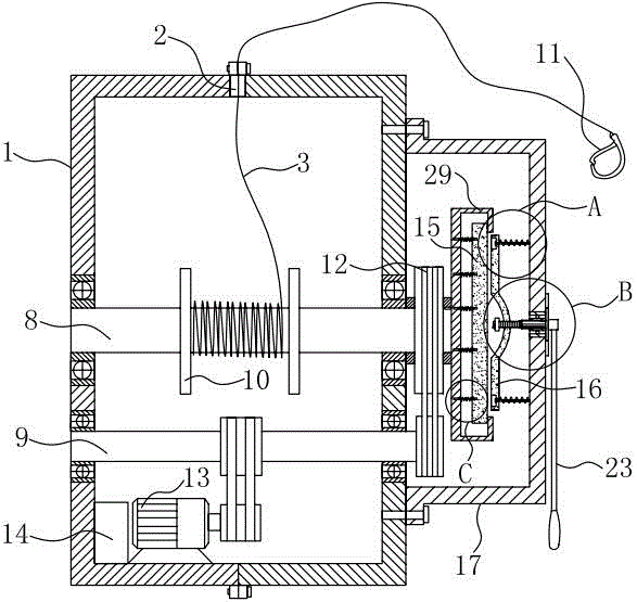
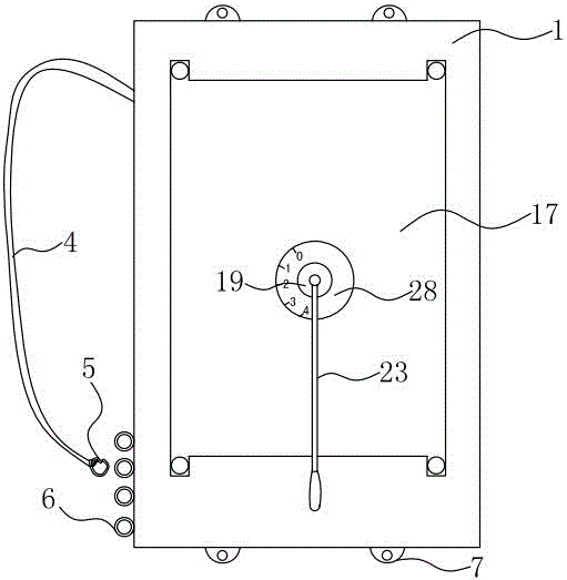
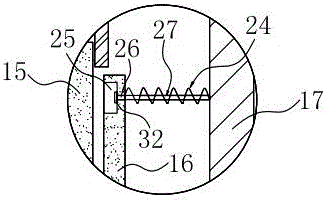
[0023] like figure 1 , 2, 3, 4, 5, 6, and 7, a new type of multifunctional descending device that can be cyclically lifted includes a housing 1 provided with a descending rope outlet 2, a friction plate and a descending rope 3, and the shell The body 1 is provided with a double-shoulder strap 4, so that the descending device can be carried on the body when escaping. One end of the double-shoulder strap 4 is fixed on the housing 1, and the other end of the double-shoulder strap 4 is provided with a buckle 5. There is a pull ring 6 for hooking the shoulder strap 4 matched with the buckle 5, the pull ring 6 is arranged vertically, in order to adapt to the crowd of different body types, the said pull ring 6 is provided with multiple, according to different people's body shape selection The pull rings 6 in different positions, in order t...


PUM


Abstract

The invention discloses a novel multifunctional descent control device with the cyclic lifting function. The novel multifunctional descent control device comprises a shell with a descent control rope outlet, a friction piece and a descent control rope. The shell is provided with shoulder straps. A rotary shaft and a transmission shaft are arranged in the shell, wherein the rotary shaft is used for mounting the friction piece, the descent control rope is wound around the rotary shaft, and the transmission shaft is used for driving the rotary shaft to rotate and winding the descent control rope. The transmission shaft is driven through a drive device. The friction piece comprises a main friction piece body and an auxiliary friction piece body which is arranged opposite to the main friction piece body and used for reducing the descent speed of the descent control device. A friction box is connected to the shell. The main friction piece body is arranged in a cavity of the friction box and fixedly connected with the rotary shaft. A control device used for adjusting the friction force of the auxiliary friction piece body and the main friction piece body is connected with the friction box in a sliding manner. The novel multifunctional descent control device further comprises a spring which is arranged between the auxiliary friction piece body and the friction box and used for increasing thrust for assisting the control device in moving the auxiliary friction piece body. The novel multifunctional descent control device is small in size, light, simple in structure, convenient to operate, safe and reliable, and time and labor are saved.

Description

technical field [0001] The invention relates to an escape device, in particular to a novel multi-function descending device which can be raised and lowered cyclically. Background technique [0002] With the rapid development of the construction industry, high-rise buildings have sprung up like bamboo shoots after a spring rain, which has brought many problems. For example, once a fire breaks out in a high-rise building, the fire spreads quickly, it is difficult to fight the fire, it is difficult to evacuate people, and it is difficult to escape from a high-rise building. It is a self-rescue method when a fire occurs. Due to the thick smoke and fire, it is difficult for people to escape normally from the stairs and elevators. Surrounded by thick smoke, poisonous gas and flames, many people were buried in the sea of ​​fire. How to escape has become an urgent problem to be solved. The invention of the descending device can enable people in danger to escape accurately on high bu...

Claims


Application Information

Patent Timeline
IPC IPC(8): A62B1/14A62B1/16
CPCA62B1/14A62B1/16
Inventor 张文革
Owner 张文革
Learn More