
Electrical equipment control method and device

A technology of electrical equipment and control devices, which is applied in the direction of electrical program control, sequence/logic controller program control, etc., and can solve problems such as single usage scenarios, energy waste, and inability to realize automatic control

Inactive Publication Date: 2016-06-15
TENCENT TECH (SHENZHEN) CO LTD
View PDF5 Cites 10 Cited by
  • Summary
  • Abstract
  • Description
  • Claims
  • Application Information

AI Technical Summary

Problems solved by technology

Therefore, the main role of the smart bracelet is just a data collector, with simple functions and a single use scene
[0003] At the same time, household appliances (such as TVs, air conditioners, etc.) can be switched to sleep mode, but in the existing technical solutions, these household appliances need to be manually set in advance or manually triggered to switch to sleep mode, so automatic control cannot be realized.
In addition, during the use of household appliances, because the user falls asleep or forgets and does not turn off the power of the appliance, energy is wasted

Method used


Image

  • Electrical equipment control method and device
  • Electrical equipment control method and device
  • Electrical equipment control method and device

Examples


Embodiment Construction

[0021] The following will clearly and completely describe the technical solutions in the embodiments of the present invention with reference to the accompanying drawings in the embodiments of the present invention. Obviously, the described embodiments are some of the embodiments of the present invention, but not all of them. Based on the embodiments of the present invention, all other embodiments obtained by persons of ordinary skill in the art without creative efforts fall within the protection scope of the present invention.

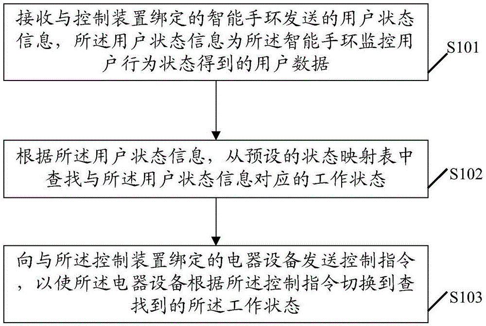
[0022] Please refer to figure 1 , figure 1 It is a flow chart of the first embodiment of an electrical equipment control method proposed by the present invention. As shown in the figure, the method in the embodiment of the present invention includes:

[0023] S101. Receive user status information sent by a smart bracelet bound to a control device, where the user status information is user data obtained by monitoring user behavior status by the smart ...


PUM


Abstract

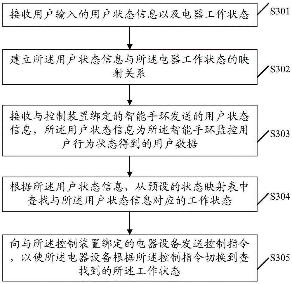
The present invention discloses an electrical equipment control method. The method comprises the steps of receiving the user state information sent by an intelligent bracelet bound to a control device, wherein the user state information contains user data obtained through monitoring the user behavior state by the intelligent bracelet; according to the user state information, searching a working state corresponding to the user state information in a preset state mapping table, wherein the preset state mapping table contains a plurality of mapping relationships between the user state information and the working state of electrical equipment; sending a control instruction to the electrical equipment bound to the control device so as to switch the electrical equipment to run in the searched working state according to the control instruction. The invention also discloses an electrical equipment control device. According to the embodiments of the invention, the electrical equipment is capable of automatically switching the working state thereof according to the user state information. Therefore, the electric energy is saved.

Description

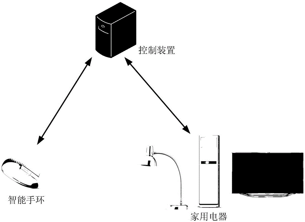
technical field [0001] The invention relates to the field of automatic control, in particular to an electrical equipment control method and device. Background technique [0002] With the vigorous development of wearable smart devices, various smart bracelets continue to emerge. The smart wristbands currently on the market mainly record real-time data such as exercise, sleep, heart rate, and diet in the user's daily life, and synchronize these real-time data to the terminal. The terminal analyzes the real-time data to obtain the user's behavior status. Therefore, the main role of the smart bracelet is just a data collector, with simple functions and a single use scenario. [0003] At the same time, household appliances (such as TVs, air conditioners, etc.) can be switched to sleep mode, but in the existing technical solutions, these household appliances need to be manually set in advance or manually triggered to switch to sleep mode, so automatic control cannot be realized. ...

Claims


Application Information

Patent Timeline
IPC IPC(8): G05B19/04
CPCG05B19/04
Inventor 俄万有
Owner TENCENT TECH (SHENZHEN) CO LTD
Learn More