
A system and method for measuring beam intensity of a particle accelerator

A particle accelerator and current intensity technology, which is applied in the field of accelerator physical beam diagnosis, can solve the problems of sensitivity to temperature difference changes and large attenuation in tunnels, and achieve the effect of improving measurement accuracy

Active Publication Date: 2018-07-13
SHANGHAI INST OF APPLIED PHYSICS - CHINESE ACAD OF SCI +1
View PDF4 Cites 0 Cited by
  • Summary
  • Abstract
  • Description
  • Claims
  • Application Information

AI Technical Summary

Problems solved by technology

[0008] The purpose of the present invention is to provide an improved system and method for measuring the beam current intensity of a particle accelerator using a common-mode TM010 signal, so as to solve the large attenuation caused by the long-distance transmission of the common-mode TM010 signal outside the tunnel in the prior art And the problem of being sensitive to the temperature difference inside and outside the tunnel, so as to improve the measurement accuracy

Method used


Image

  • A system and method for measuring beam intensity of a particle accelerator
  • A system and method for measuring beam intensity of a particle accelerator
  • A system and method for measuring beam intensity of a particle accelerator

Examples


Embodiment Construction

[0029] Below in conjunction with the drawings, preferred embodiments of the present invention are given and described in detail.

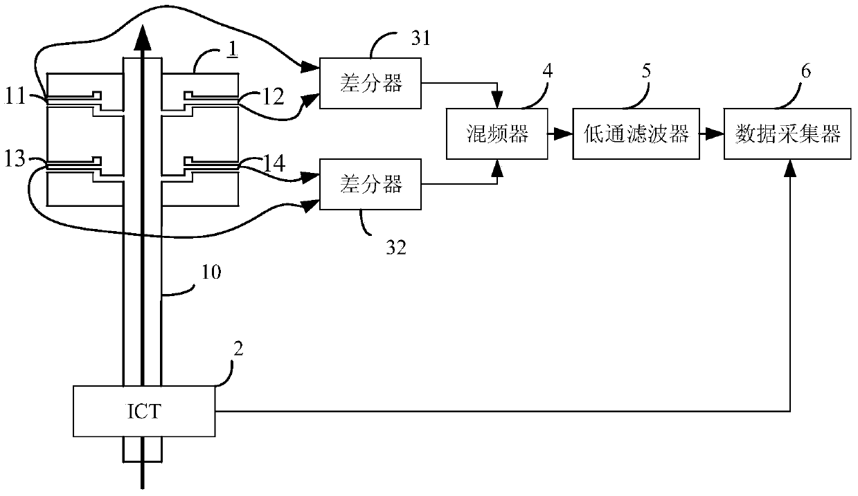
[0030] Such as figure 1 As shown, the present invention, that is, the system for measuring the beam current intensity of a particle accelerator, includes a double-cavity BPM1 and an ICT2 arranged on the particle accelerator channel 10, and also includes a pair of differentiators 31 and 32 for signal processing, A mixer 4 , a low-pass filter 5 and a data collector 6 . Among them, the mixer 4 , the low-pass filter 5 and the data collector 6 are connected in series sequentially, and a pair of differentiators 31 and 32 are connected in parallel between the double-cavity BPM1 and the mixer 4 .

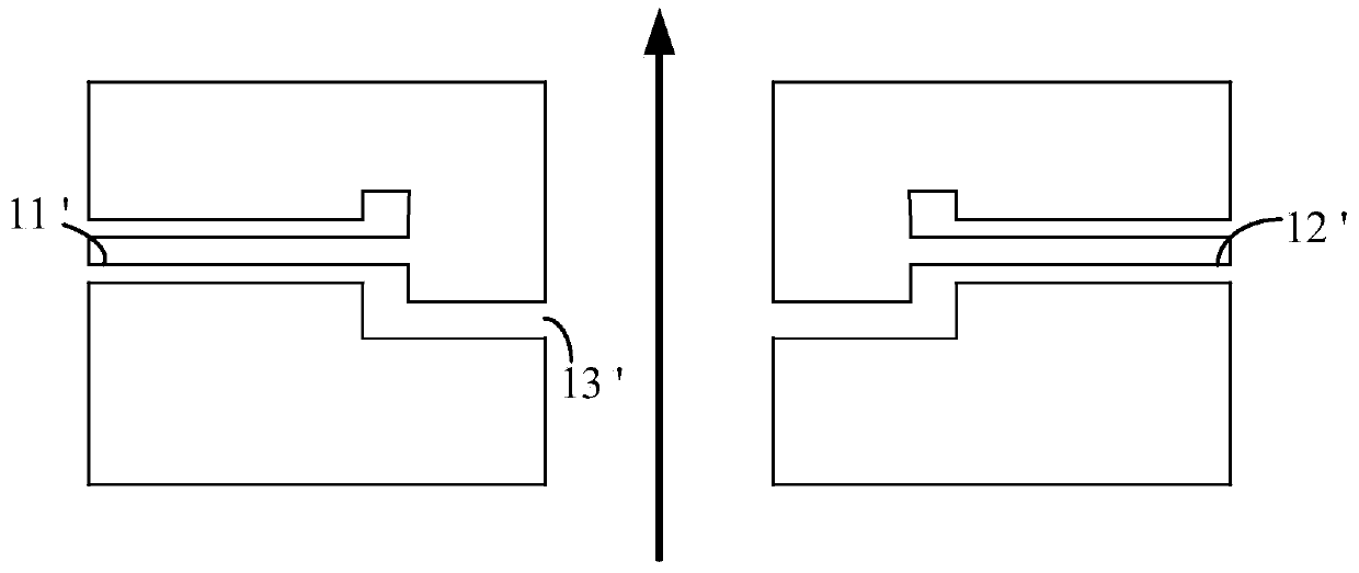
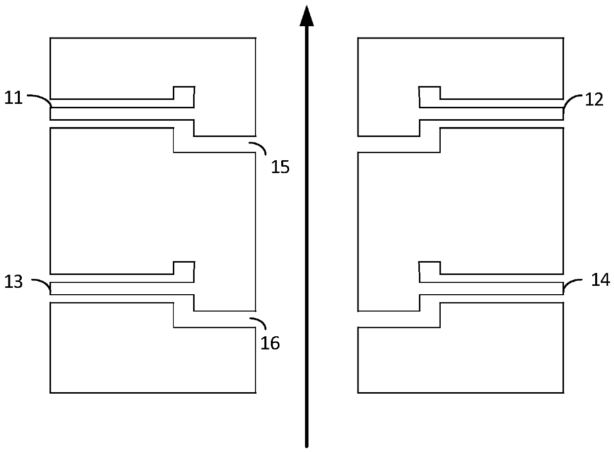
[0031] In the present invention, the double-cavity BPM1 refers to a beam position detector with a reference cavity added on the basis of a typical cavity BPM, figure 2 with image 3 The structural schematic diagrams of a typical cavity type BPM and a double ...


PUM


Abstract

The invention provides a system for measuring the beam flow intensity of a particle accelerator. The system comprises a dual-chamber chamber-type BPM and an ICT both arranged on a particle accelerator. The BPM comprises two reference chambers, each of which comprises a pair of probes on two sides respectively. The system also comprises a pair of differentiators, a mixer, a low-pass filter and a data collector. The mixer, the low pass filter and the data collector are connected in series successively. The pair of differentiators are connected between the BPM and the mixer parallelly. The system overcomes the defect in the prior art that a common mode TM010 signal must be transmitted for a long distance to the outside of a tunnel for mixing with a downconverted local oscillator source so that the signal is attenuated and is sensitive to the indoor and outdoor temperature difference, so that the measurement precision is improved.

Description

technical field [0001] The invention relates to the field of accelerator physics beam diagnosis, in particular to a system and method for measuring beam intensity in a particle accelerator. Background technique [0002] At present, ICT (Integrating Current Transformer) has been widely used in particle accelerators to measure beam current intensity ("beam current intensity" mentioned in this application refers to the amplitude of beam current intensity). However, since the measurement waveform of ICT is greatly disturbed by the ground loop, if ICT is used for a single measurement, the random error will be large, which cannot meet the requirements of measurement accuracy; but if ICT is used for multiple measurements, the average value obtained is accurate It can be used for flow intensity calibration. [0003] Cavity BPM (Beam Position Probe) is an existing signal acquisition method, which is widely used in particle accelerators for position measurement due to its nm-level po...

Claims


Application Information

Patent Timeline
Patent Type & Authority Patents(China)
IPC IPC(8): G01T1/29
CPCG01T1/29
Inventor 冷用斌赖龙伟阎映炳袁任贤
Owner SHANGHAI INST OF APPLIED PHYSICS - CHINESE ACAD OF SCI
Learn More