
Structure and Construction Method of Hollow Slab Wide Bridge with Batch Transverse Stretch Strengthening Hinge Joints

A technology of transverse stretching and hollow slabs, applied in bridges, bridge parts, bridge construction, etc., can solve problems such as deflection and reverse arching on wide bridges with hollow slabs, effective prestress cannot be guaranteed, and bonding force of joint surfaces cannot be guaranteed. , to achieve the effect of overcoming the transverse prestress tension and simple structure

Active Publication Date: 2017-10-20
福建省陆海工程科技有限公司
View PDF7 Cites 0 Cited by
  • Summary
  • Abstract
  • Description
  • Claims
  • Application Information

AI Technical Summary

Problems solved by technology

[0004] For prefabricated wide bridges with hollow slabs, due to the large width of the bridge, if the transverse prestressed steel tendons are stretched at one time along the entire length of the transverse bridge, the effective prestress after transverse stretching cannot be guaranteed, so that the improvement of the hollow slab cannot be ensured. The adhesive strength of the joint surface between the hinge joint and the hollow slab wide bridge will appear upward deflection and anti-arch in the transverse bridge direction

Method used


Image

  • Structure and Construction Method of Hollow Slab Wide Bridge with Batch Transverse Stretch Strengthening Hinge Joints
  • Structure and Construction Method of Hollow Slab Wide Bridge with Batch Transverse Stretch Strengthening Hinge Joints
  • Structure and Construction Method of Hollow Slab Wide Bridge with Batch Transverse Stretch Strengthening Hinge Joints

Examples


Embodiment Construction

[0030] In order to make the above-mentioned features and advantages of the present invention more comprehensible, the following specific embodiments are described in detail with reference to the accompanying drawings, but the present invention is not limited thereto.

[0031] refer to Figure 1 to Figure 7

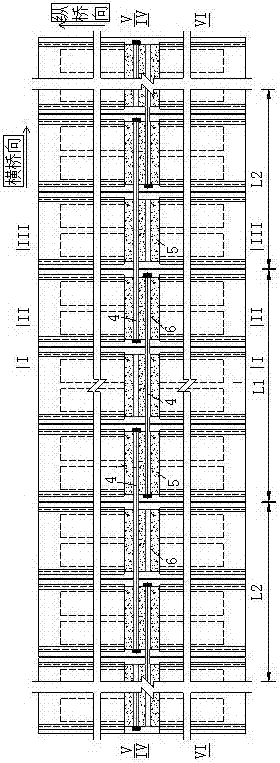
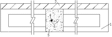
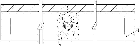
[0032] A wide bridge structure of hollow slabs reinforced with transverse stretching in batches, including prefabricated hollow slabs 1 arranged in parallel along the direction of the transverse bridge, and hinged joints 2 are arranged between two adjacent prefabricated hollow slabs, located between the prefabricated hollow slabs and A bridge deck pavement layer 3 is poured above the hinge joint, and prestressed steel tendons 4 are stretched transversely in batches inside the prefabricated hollow slab.

[0033] In this embodiment, when the span of the prefabricated hollow slab is 6m-10m, a diaphragm structure 5 is provided on the mid-span section of each prefabricated hol...


PUM


Abstract

The invention relates to a hollow slab wide bridge structure for reinforcing hinge joints through batch transverse tensioning and a construction method of the hollow slab wide bridge structure.The hollow slab wide bridge structure comprises prefabricated hollow slabs which are arranged continuously in the transverse direction of a bridge side by side, each hinge joint is arranged between every two adjacent prefabricated hollow slabs, a bridge surface pavement layer is poured above the prefabricated hollow slabs and the hinge joints, and prestressed steel beams are tensioned transversely in batches inside the prefabricated hollow slabs.The construction method comprises the steps of prefabricating the hollow slabs; hoisting the first batch of prefabricated hollow slab sets, and making the first batch of prestressed steel beams penetrate through the first batch of prefabricated hollow slab sets; pouring hinge joint concrete among the first batch of prefabricated hollow slab sets, after design strength is achieved, tensioning the prestressed steel beams transversely, and conducting grouting and anchor sealing; hoisting the second batch of prefabricated hollow slab sets, and meanwhile making the second batch of prestressed steel beams penetrate; conducting the batch transverse tensioning construction procedure of remaining prefabricated hollow slab sets as mentioned till the prestressed steel beams are tensioned completely; pouring the bridge surface pavement layer, and forming the bridge after strength of the bridge surface pavement layer is achieved.The hollow slab bridge is simple in structure, and in addition, the transverse prestressed tensioning defects of an assembly type hollow slab wide bridge are effectively overcome.

Description

technical field [0001] The invention relates to a hollow slab wide bridge structure and a construction method thereof which are transversely stretched in batches to strengthen hinge joints. Background technique [0002] According to relevant data, as of 2010, the proportion of prefabricated hollow slab girder bridges in my country's highway bridge system reached 64%. This type of bridge has the advantages of low building height, easy prefabrication, and simple design and construction. At present, the horizontal connection between prefabricated hollow slab bridges is mainly composed of deep and wide hinge joints. Relevant studies have shown that when no structural reinforcement is provided at the joint surface between the hollow slab and the hinge joint, the joint surface will be the earliest under the action of vehicle load. When cracking occurs, as the vehicle load increases, the joint surface extends from the mid-span section to both ends in the longitudinal bridge direct...

Claims


Application Information

Patent Timeline
Patent Type & Authority Patents(China)
IPC IPC(8): E01D12/00E01D19/00E01D21/00
CPCE01D12/00E01D19/00E01D21/00
Inventor 陈康明吴庆雄陈宝春韦建刚蔡永利
Owner 福建省陆海工程科技有限公司
Learn More