Screen projecting method and projecting target side device

An end device and target end technology, applied in the field of screen projection method and projection target end device, can solve the problem of no discovery and so on

Inactive Publication Date: 2016-06-08
AUTOCHIPS
View PDF4 Cites 6 Cited by
  • Summary
  • Abstract
  • Description
  • Claims
  • Application Information

AI Technical Summary

Problems solved by technology

At present, no corresponding technology has

Method used


Image

  • Screen projecting method and projecting target side device
  • Screen projecting method and projecting target side device
  • Screen projecting method and projecting target side device

Examples


Embodiment Construction

[0018] The technical solutions in the embodiments of the present invention will be described clearly and completely with reference to the accompanying drawings in the embodiments of the present invention. Obviously, the described embodiments are only a part of the embodiments of the present invention, not all the embodiments. Based on the embodiments of the present invention, all other embodiments obtained by those of ordinary skill in the art without creative work shall fall within the protection scope of the present invention.

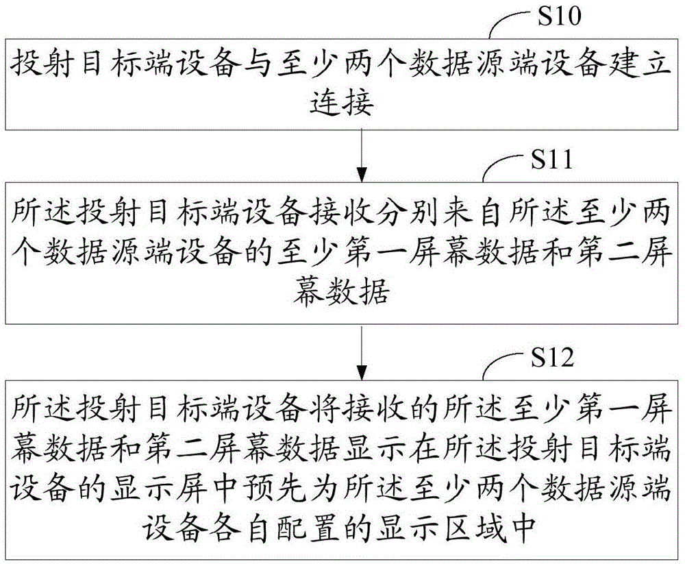
[0019] figure 1 It is a schematic flowchart of the screen projection method of the first embodiment of the present invention. Such as figure 1 As shown, the screen projection methods include:

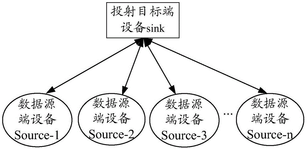
[0020] Step S10: The projection target device establishes a connection with at least two data source devices.

[0021] In the embodiment of the present invention, any one of the data source device and the projection target device includes but is not limited to handh...


PUM


Abstract

The invention discloses a screen projecting method and a projecting target side device. The method comprises the steps that network connection between the projecting target side device and at least two data source side devices is established; the projecting target side device receives screen data sent by the data source side devices through the established connection; the received screen data sent by the data source side devices is displayed in display areas configured for the data source side devices in advance on a display screen of the projecting target side device. In this way, screen projections of a plurality of data source side devices can be displayed on the screen of one projecting target side device, and the user experience is improved.

Description

Technical field [0001] The present invention relates to the field of screen projection technology, in particular to a screen projection method and projection target terminal equipment. Background technique [0002] The current mainstream multi-screen interactions, such as Cloud Play (AirPlay), Digital Life Network Alliance (DIGITALLIVINGNETWORKALLIANCE, DLNA) and Wireless Display (Miracast), only support a single data source device (usually called "source") to a single Projection target device (usually called "sink end"), or a single data source device to multiple projection target devices. However, in practical applications, sometimes it is necessary to compare text, pictures, tables, and even video data from different data source devices on a large screen; sometimes it is necessary to divide the screen data of multiple data source devices into regional Projected onto a large screen, allowing multiple data source devices to participate in a process, such as a game. However, no...

Claims


Application Information

Patent Timeline
IPC IPC(8): G06F3/14
CPCG06F3/1438
Inventor 李正鹏
Owner AUTOCHIPS
Why Eureka
Try Eureka