
Insulator Leakage Current Monitoring System for Laboratory

A leakage current and monitoring system technology, applied in the direction of measuring current/voltage, voltage/current isolation, measuring electricity, etc., can solve the problems of monitoring system error reporting, increasing the incidence of pollution flashover accidents, monitoring equipment damage, etc., to ensure long-lasting Stable operation, favorable for reliable analysis, and long service life

Active Publication Date: 2019-04-23
GUANGZHOU POWER SUPPLY BUREAU GUANGDONG POWER GRID CO LTD +1
View PDF6 Cites 0 Cited by
  • Summary
  • Abstract
  • Description
  • Claims
  • Application Information

AI Technical Summary

Problems solved by technology

[0002] In a humid environment, the dirty layer on the surface of the insulator becomes moist due to the influence of humid air, which leads to an increase in the leakage current on the surface of the insulator, resulting in a significant decrease in the electrical strength of the insulator, increasing the incidence of pollution flashover accidents, and seriously threatening The operation safety of the power system, therefore, is crucial for the monitoring of insulator leakage current
[0003] In the prior art, the leakage current of insulators in the laboratory has the following defects: poor anti-interference, resulting in many glitches in the finally monitored leakage current signal, resulting in errors reported by the monitoring system, resulting in false alarms and affecting the performance analysis of insulators; using Short life, easy to cause damage to monitoring equipment when flashover occurs on the surface of the insulator

Method used


Image

  • Insulator Leakage Current Monitoring System for Laboratory
  • Insulator Leakage Current Monitoring System for Laboratory
  • Insulator Leakage Current Monitoring System for Laboratory

Examples


Embodiment Construction

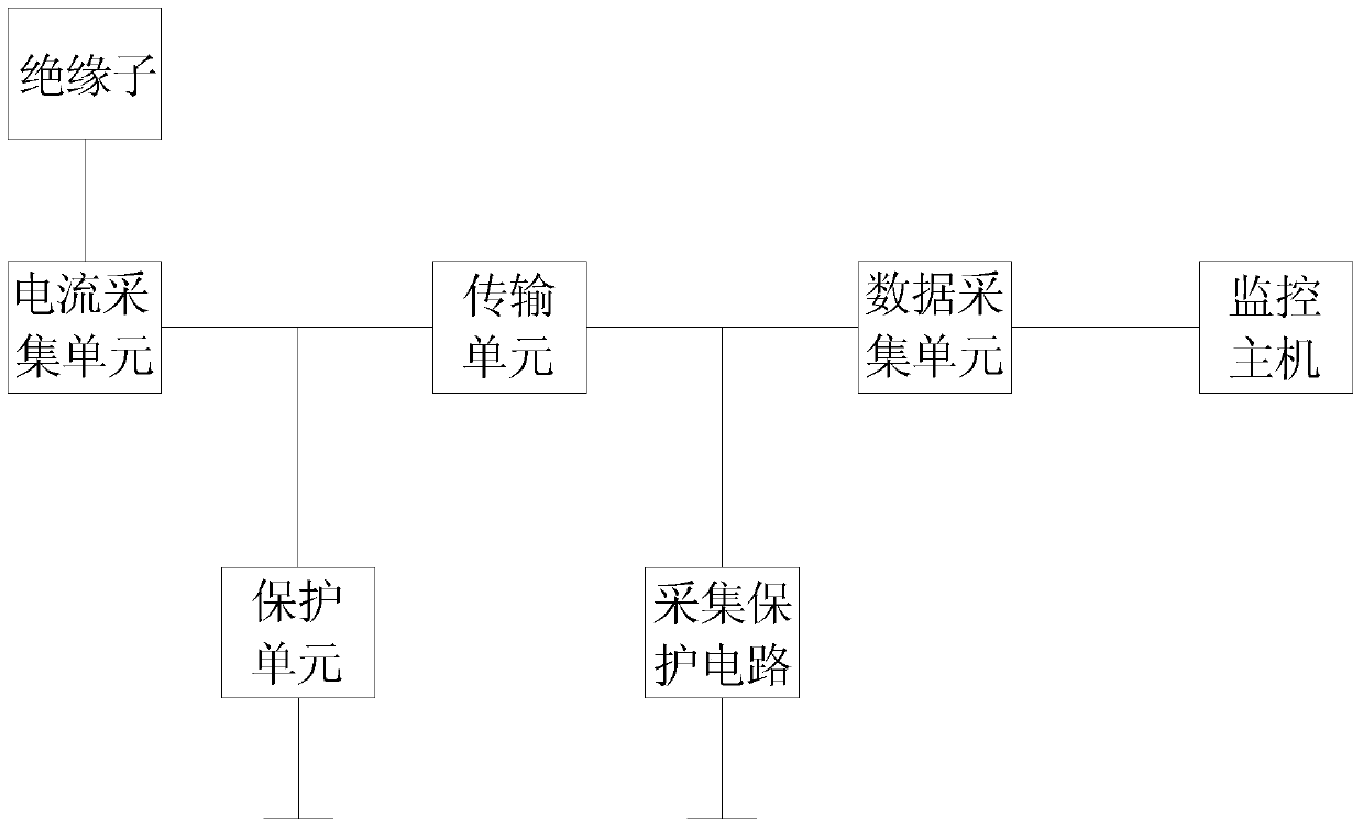
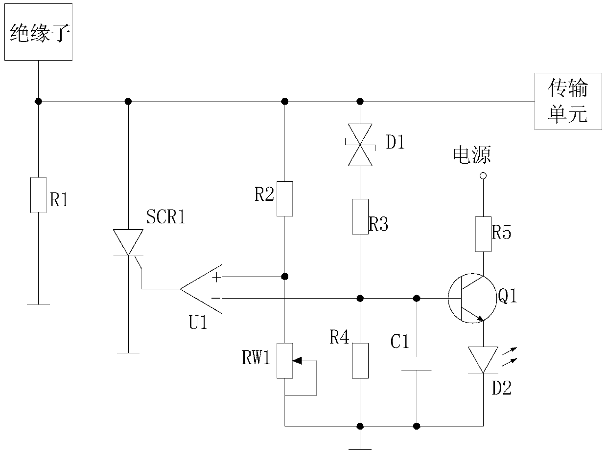
[0018] figure 1 It is a block diagram of the present invention, figure 2 It is the circuit principle diagram of the present invention, as shown in the figure, the insulator leakage current monitoring system used in the laboratory provided by the present invention includes a current acquisition unit for collecting the insulator leakage current, and a current acquisition unit connected to the output end of the current acquisition unit. An isolated transmission unit, a data acquisition unit connected to the isolated transmission unit, and a monitoring host connected to the data acquisition unit; the output end of the current acquisition unit is provided with a protection unit, wherein the data acquisition unit adopts a data acquisition card; The insulator leakage current monitoring system used in the laboratory provided by the invention, on the one hand, can accurately detect the leakage current on the surface of the insulator, which is conducive to reliable analysis of the work...


PUM


Abstract

The invention provides an insulator leakage current monitoring system used for a laboratory. The system comprises a current acquisition unit, an isolation transmission unit, a data acquisition unit and a monitoring host, wherein the current acquisition unit is used for collecting an insulator leakage current; the isolation transmission unit is connected to an output terminal of the current acquisition unit; the data acquisition unit is connected to the isolation transmission unit; and the monitoring host is connected to the data acquisition unit. The output terminal of the current acquisition unit is provided with a protection unit. On one hand, the leakage current on an insulator surface can be accurately detected, which is good for reliably analyzing a work state of the insulator; on the other hand, the monitoring system can be effectively protected, the monitoring system is guaranteed to be operated durably and stably and a service life is prolonged.

Description

technical field [0001] The invention relates to a power equipment monitoring system, in particular to a laboratory insulator leakage current monitoring system. Background technique [0002] In a humid environment, the dirty layer on the surface of the insulator becomes moist due to the influence of humid air, which leads to an increase in the leakage current on the surface of the insulator, resulting in a significant decrease in the electrical strength of the insulator, increasing the incidence of pollution flashover accidents, and seriously threatening The operation safety of the power system, therefore, is crucial to the monitoring of insulator leakage current. [0003] In the prior art, the leakage current of insulators in the laboratory has the following defects: poor anti-interference, resulting in many glitches in the finally monitored leakage current signal, resulting in errors reported by the monitoring system, resulting in false alarms and affecting the performance ...

Claims


Application Information

Patent Timeline
Patent Type & Authority Patents(China)
IPC IPC(8): G01R19/00G01R31/02G01R15/14G01R1/18
Inventor 张志劲陆国俊蒋兴良黄青丹宋浩永张东东何彬彬
Owner GUANGZHOU POWER SUPPLY BUREAU GUANGDONG POWER GRID CO LTD
Learn More