
Light sensor calibration method and device

A light sensor and calibration method technology, which is applied in the direction of comparing with the reference electrical parameters, etc., can solve the problem of low accuracy of light illuminance measurement

Active Publication Date: 2016-06-08
XIAOMI INC
View PDF5 Cites 10 Cited by
  • Summary
  • Abstract
  • Description
  • Claims
  • Application Information

AI Technical Summary

Problems solved by technology

[0003] In practical applications, the light sensor may be sensitive to the color temperature, that is, the light sensor may have a large difference in the measurement value of the same illuminance light in different color temperature environments, which leads to the measurement accuracy of the light sensor for the light illuminance. In addition, the measurement accuracy of the light sensor to the light illuminance is also affected by the assembly of the light sensor, materials, etc. Therefore, there is an urgent need for a method of calibrating the light sensor to improve the measurement accuracy of the light sensor to the light illuminance

Method used


Image

  • Light sensor calibration method and device
  • Light sensor calibration method and device
  • Light sensor calibration method and device

Examples


Embodiment Construction

[0074] In order to make the purpose, technical solution and advantages of the present disclosure clearer, the implementation manners of the present disclosure will be further described in detail below in conjunction with the accompanying drawings.

[0075] Reference will now be made in detail to the exemplary embodiments, examples of which are illustrated in the accompanying drawings. When the following description refers to the accompanying drawings, the same numerals in different drawings refer to the same or similar elements unless otherwise indicated. The implementations described in the following exemplary examples do not represent all implementations consistent with the present disclosure. Rather, they are merely examples of apparatuses and methods consistent with aspects of the present disclosure as recited in the appended claims.

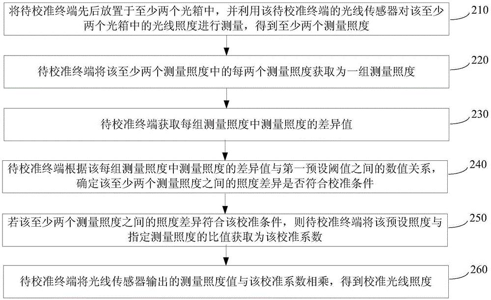
[0076] figure 1 It is a flow chart of a light sensor calibration method shown according to an exemplary embodiment, such as figure 1 As ...


PUM


Abstract

The invention provides a light sensor calibration method and device, and belongs to the technical field of terminals. The method comprises the steps that the light sensor of a terminal under calibration is applied to detect at least two preset light environments so that at least two measured illumination is obtained, and the at least two preset light environments have the same preset illumination and different color temperature; whether the illumination difference between the at least two measured illumination meets standard conditions is detected; and if the illumination difference between the at least two measured illumination meets the standard conditions, the calibration coefficient is obtained according to the preset illumination and the at least two measured illumination, and the calibration coefficient is used for calibrating the light sensor of the terminal under calibration. According to the technical scheme, measurement of illumination through the light sensor is enabled to be more accurate.

Description

technical field [0001] The present disclosure relates to the technical field of terminals, in particular to a method and device for calibrating a light sensor. Background technique [0002] With the development of science and technology, mobile terminals have become more and more common in people's lives, and users have higher and higher performance requirements for mobile terminals. Among them, the battery life and screen clarity of mobile terminals are the performance that users are more concerned about. Indicators, in order to improve these two performance indicators and meet the user's requirements for mobile terminal performance, currently, mobile terminals are generally equipped with light sensors, which can be used to detect the illuminance of light in the environment where the mobile terminal is located, so that the mobile terminal Adjust the brightness of the screen and the on and off of the keyboard light according to the light illuminance detected by the light sen...

Claims


Application Information

Patent Timeline
IPC IPC(8): G01J1/10
CPCG01J1/10
Inventor 王中帅马宁杨依珍
Owner XIAOMI INC
Learn More