
A built-in diaphragm sleeve valve

A sleeve valve and diaphragm-type technology, applied in valve details, safety valves, balance valves, etc., can solve problems such as poor anti-garbage ability, poor energy dissipation effect, and non-linear flow regulation, and achieve cost reduction and structure Simple, Powerful Effects

Active Publication Date: 2017-11-28
SHANGHAI KARON VALVES MACHINERY +1
View PDF6 Cites 0 Cited by
  • Summary
  • Abstract
  • Description
  • Claims
  • Application Information

AI Technical Summary

Problems solved by technology

[0002] The commonly used sleeve valve types in the water supply system are fixed cone type, multi-nozzle type, piston valve, curved neck type (Y type), etc. The opening and closing of these valves must be driven by external force (electric device or cylinder). Some products have complex structure and large installation space, and are expensive; some products have poor energy dissipation effect; some products have poor fluidity and poor cavitation resistance; some products have poor anti-garbage ability and are prone to failure; , but due to the need to rely on electric equipment to drive, and the larger the surface area, the higher the cost, and at the same time the current regulation is not linear

Method used


Image

  • A built-in diaphragm sleeve valve
  • A built-in diaphragm sleeve valve
  • A built-in diaphragm sleeve valve

Examples


Embodiment 1

[0041] The present invention can work in pressure reducing valve mode, such as Figure 4 As shown, the working principle of the pressure reducing valve is:

[0042] The principle is that the pressure signal collected by the pressure sensor behind the valve is transmitted to the remote central control PLC, and then the PLC controls the main valve. Once the downstream flow increases and the pressure drops, the sensor immediately sends a signal to the PLC, the PLC immediately instructs to open the solenoid valves B and D, the opening of the main valve increases, and the pressure immediately recovers to the design value, and the solenoid valves B and D are closed; When the flow decreases and the pressure rises, the PLC will instruct to open the solenoid valves A and C, the opening of the main valve decreases, and the pressure returns to the set value, and the solenoid valves A and C are closed.

Embodiment 2

[0044] The present invention can work in pressure relief valve mode, such as Figure 5 As shown, the working principle of the pressure relief valve is:

[0045] The principle is that the pressure signal collected by the pressure sensor in front of the valve is transmitted to the remote central control PLC, and then the PLC controls the main valve. Once the system pressure rises above the set pressure, the sensor immediately sends a signal to the PLC, the PLC immediately instructs to open solenoid valves B and D, close solenoid valves A and C, and the main valve immediately opens to relieve pressure; otherwise, the system pressure is lower than the set value , the PLC command closes solenoid valves B and D, opens solenoid valves A and C, and the main valve is closed.

Embodiment 3

[0047] The present invention can work in flow control valve mode, such as Image 6 As shown, the flow control valve works as follows:

[0048]Once the remote central control PLC sets the standard given flow, the signal detected by the flowmeter will be fed back to the PLC immediately. If the flow exceeds the given value, the PLC will send a signal command to open solenoid valves A and C (solenoid valves B and D are closed). ), the pressure in the front chamber of the diaphragm drops, and the main valve closes the valve, then the flow rate is reduced to the given value; if the flow rate is lower than the given value, the flowmeter will feed back the signal to the PLC, and the central control will send an instruction to open the solenoid valve B, D (solenoid valves A and C are closed), the pressure in the back cavity of the diaphragm drops, and the main valve opens to supplement the flow to the given value.

[0049] Figure 7 The piping diagram of the pneumatic control valve r...


PUM


Abstract

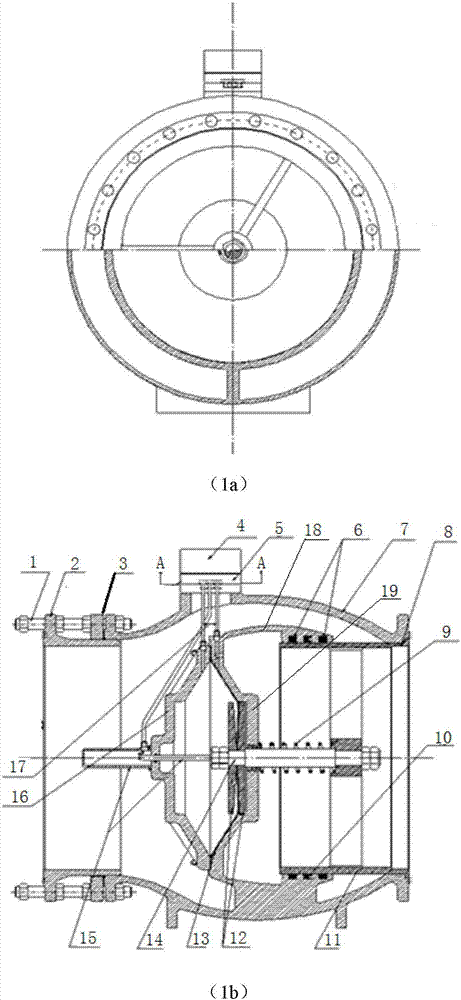
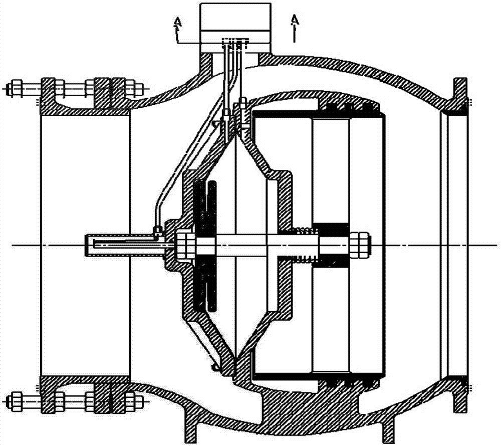
The invention relates to a built-in diaphragm type sleeve valve. The built-in diaphragm type sleeve valve comprises a valve body, a sleeve gate arranged in the valve body, and a valve base mounted on a flange in an outlet of the valve body. The sleeve valve further comprises a control component, a movement component and a diaphragm cavity component; the control component is arranged above the valve body; the movement component and the diaphragm cavity component are arranged in the valve body; the back end of the movement component is connected with the control component through a distribution pipe, and the front end is connected with the sleeve gate by penetrating through the diaphragm cavity component; and when the sleeve valve performs an opening / closing action, the control component detects and controls pressure in the diaphragm cavity component through the distribution pipe so as to control the movement component to drive the sleeve gate to move so as to realize the opening / closing action of the valve. Compared with the prior art, the built-in diaphragm type sleeve valve has such advantages as simple structure, low cost, good fluid state, excellent energy dissipation and cavitation resistance, multiple driving modes, powerful functions, low opening / closing force and reduction of extension connecting cost.

Description

technical field [0001] The invention relates to a sleeve valve, in particular to a built-in diaphragm type sleeve valve. Background technique [0002] The commonly used sleeve valve types in the water supply system include fixed cone type, multi-nozzle type, piston valve, curved neck type (Y type), etc. The opening and closing of these valves must be driven by external force (electric equipment or cylinder). Some products have complex structure and large installation space and are expensive; some products have poor energy dissipation effect; some products have poor flow state and poor cavitation resistance; some products have poor resistance to garbage and are prone to failure; only piston valves are similar to this valve , but because it must be driven by electrical equipment, and the cost is higher due to the larger space between the surfaces, and the current regulation is not linear. SUMMARY OF THE INVENTION [0003] The purpose of the present invention is to provide a...

Claims


Application Information

Patent Timeline
Patent Type & Authority Patents(China)
IPC IPC(8): F16K17/26F16K31/128F16K37/00F16K27/04
CPCF16K17/26F16K27/041F16K31/1266F16K31/128F16K37/0008
Inventor 李政宏
Owner SHANGHAI KARON VALVES MACHINERY
Learn More