A vehicle radar mounting bracket

A technology for installing brackets and radars, which is applied to vehicle components, transportation and packaging, etc. It can solve problems such as changes in the position of brackets, and achieve high-precision adjustments

Active Publication Date: 2017-10-13
HELLA SHANGHAI ELECTRONICS
View PDF5 Cites 0 Cited by
  • Summary
  • Abstract
  • Description
  • Claims
  • Application Information

AI Technical Summary

Problems solved by technology

However, at present, the radar bracket adopts a fixed structure. When the simulation data is adjusted or the driving habits of the car owner change, and the auxiliary radar angle or space position needs to be adjusted, the position and placement angle of the bracket cannot be changed, and a matching radar mounting bracket needs to be remade.

Method used


Image

  • A vehicle radar mounting bracket
  • A vehicle radar mounting bracket
  • A vehicle radar mounting bracket

Examples


Embodiment Construction

[0042] The advantages of the present invention will be further elaborated below in conjunction with the accompanying drawings and specific embodiments.

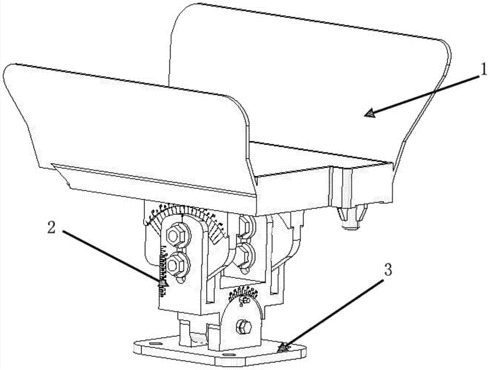
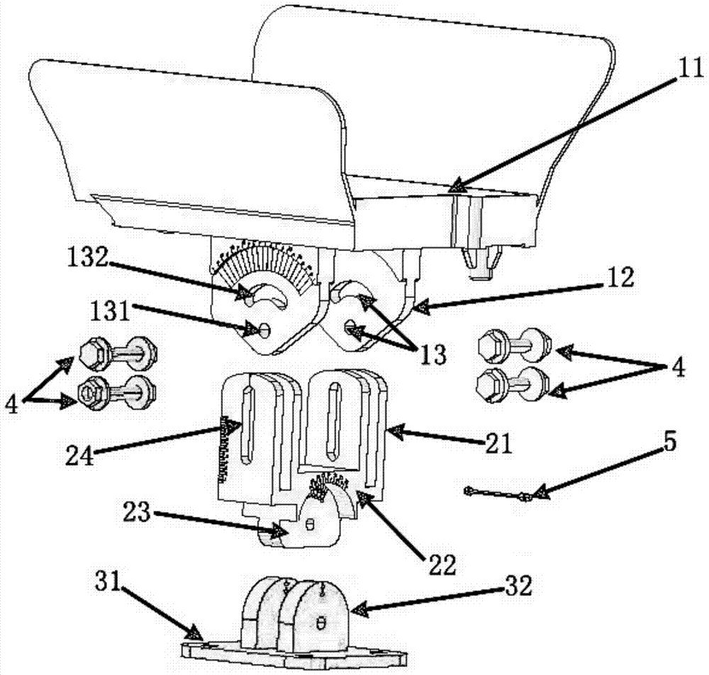
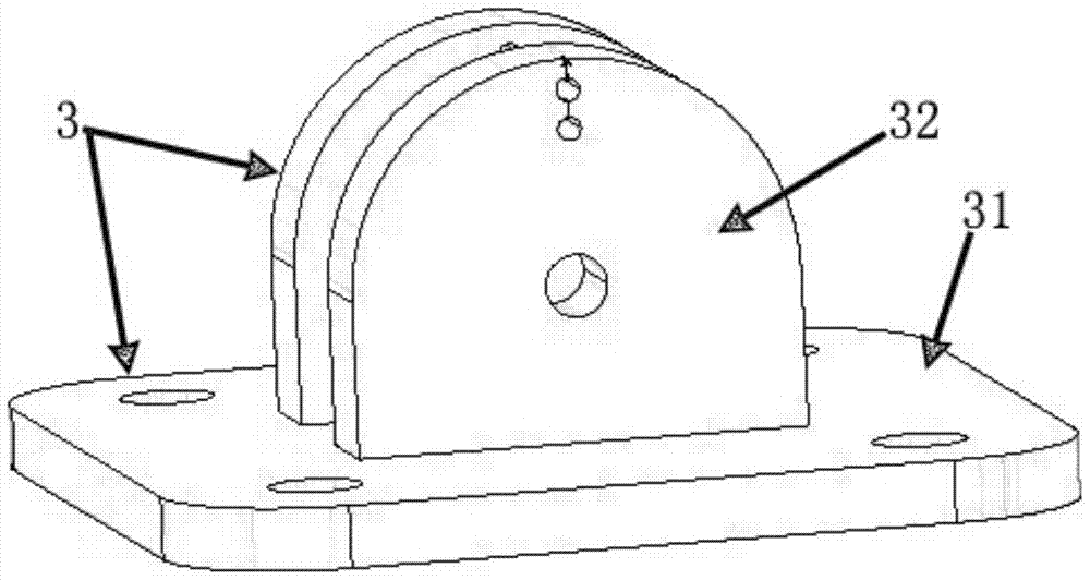
[0043] refer to figure 1 and figure 2 , are respectively a perspective view and an exploded view of the mounting bracket in a preferred embodiment of the present invention. In this embodiment, the vehicle radar mounting bracket includes a base 3 , a transmission bracket 2 and a bearing bracket 1 . The supporting bracket 1 is used to support the radar (not shown). The base 3 is fixed on the vehicle body, and serves as a supporting component for the transmission bracket 2, the bearing bracket 1 and the radar. The base 3 is also hingedly connected to the transmission bracket 2 at the same time, so that the transmission bracket 2 can rotate around the hinge point as a fulcrum. Specifically, the transmission bracket 2 includes at least one connecting portion 21 , and the bearing bracket 1 includes a bearing portion 11 and at ...


PUM


Abstract

The invention provides a vehicle radar mounting bracket, which includes a base, a transmission bracket and a bearing bracket; the transmission bracket includes at least one connecting part, and the bearing bracket includes a bearing part and at least one fixing part; The seat is hingedly connected with the transmission bracket; the connecting part is provided with a connecting through hole penetrating in a direction perpendicular to the longitudinal section of the connecting part; the fixed part is provided with at least two fixing through holes, and each fixing through hole is vertically The direction of the section runs through; it also includes at least two fixing members connecting the connecting part and the fixing part; at least two fixing members penetrate through the connecting through hole and any two or more fixing through holes, and the fixing member slides and \ Or slide relative to the fixing through hole, so that the fixing part moves relative to the connecting part. Through the installation bracket of the present invention, the radar can be adjusted in the six directions of up and down, left and right, and front and rear, and parameters such as adjustment angle and distance can be directly read.

Description

technical field [0001] The invention relates to a mounting bracket, in particular to a vehicle radar mounting bracket. Background technique [0002] In the existing technology, due to the precise requirements for the placement angle and spatial position of the auxiliary radar, it is necessary to carry out pre-simulation for different models and driving habits of different car owners, and then make a radar bracket sample. However, at present, the radar bracket adopts a fixed structure. When the simulation data is adjusted or the driving habits of the car owner change, and the auxiliary radar angle or spatial position needs to be adjusted, the position and placement angle of the bracket cannot be changed, and a matching radar mounting bracket needs to be remade. [0003] Therefore, there is a need for a new type of radar mounting bracket, which can adjust the position and detection angle of the bracket arbitrarily according to different models and driving habits of different c...

Claims


Application Information

Patent Timeline
Patent Type & Authority Patents(China)
IPC IPC(8): B60R11/00
Inventor 李健刘瑞庭
Owner HELLA SHANGHAI ELECTRONICS
Why Eureka
Try Eureka