
Backlight module group, light transmission uniformity detection system therefor, and LED mixed bead matching method for backlight module group

A detection system and backlight module technology, applied in the testing of optical performance, light source, electric light source, etc., can solve the problems of reducing product market competitiveness, decreasing uniformity of light output, affecting user experience, etc., and achieving high display brightness and Display uniformity, high brightness effect

Active Publication Date: 2016-06-01
深圳英伦科技股份有限公司 +1
View PDF10 Cites 9 Cited by
  • Summary
  • Abstract
  • Description
  • Claims
  • Application Information

AI Technical Summary

Problems solved by technology

Ordinary display modules usually lead to a decrease in the uniformity of light transmission of the screen when they are of a certain size.
Moreover, for large-area splicing walls, advertising screens, etc., it needs to be formed by splicing multiple common display modules, but because the splicing effect cannot achieve a perfect construction, it will make the large-area splicing walls, advertising screens, etc. emit light as a whole. The uniformity will be reduced, so the problem of uniformity of the overall screen light needs to be further solved
[0003] Of course, it is also possible that in order to achieve different display effects, the display module needs to continuously attach films with different functions on the display screen, and the interaction of each film makes the incident light emitted by the backlight module pass through the display screen. A consistent light output effect cannot be obtained, which makes the display brightness not uniform enough to meet the technical requirements for further improving the uniformity of light output. Market Competitiveness

Method used


Image

  • Backlight module group, light transmission uniformity detection system therefor, and LED mixed bead matching method for backlight module group
  • Backlight module group, light transmission uniformity detection system therefor, and LED mixed bead matching method for backlight module group
  • Backlight module group, light transmission uniformity detection system therefor, and LED mixed bead matching method for backlight module group

Examples


Embodiment Construction

[0029] In order to facilitate the understanding of the present invention, the present invention will be described more fully below with reference to the associated drawings. Preferred embodiments of the invention are shown in the accompanying drawings. However, the present invention can be embodied in many different forms and is not limited to the embodiments described herein. On the contrary, the purpose of providing these embodiments is to make the disclosure of the present invention more thorough and comprehensive.

[0030] It should be noted that when an element is referred to as being “fixed” to another element, it can be directly on the other element or there can also be an intervening element. When an element is referred to as being "connected to" another element, it can be directly connected to the other element or intervening elements may also be present. The terms "vertical," "horizontal," "left," "right," and similar expressions are used herein for purposes of ill...


PUM


Abstract

The invention relates to a backlight module group, a light transmission uniformity detection system therefor, and an LED mixed bead matching method for the backlight module group. The method comprises the steps: detection, calculation and mixed matching. The method selects a plurality of LED chips with different luminous fluxes and / or light outgoing angles, and the plurality of LED chips are corresponding to a plurality of positions on a display screen, so as to compensate the brightness difference caused by the difference of light transmittance of the display screen at different positions, to achieve the fine tuning of the brightness of the display screen at different positions, and to finally enable the display brightness of the display screen to be uniform. Meanwhile, the display screen is a 2D, naked-eye 3D or glasses-type 3D display screen, and the above method can enable the uniformity of the display brightness of the display screen to be improved to 95% or more, thereby achieving the high-definition or ultra-high-definition display, and enabling the backlight module group to be higher in brightness, reliability and uniformity so s to meet the demands of a joint wall product or single-machine product with higher requirements for uniformity, such as a monitoring room joint screen, a single machine, a joint screen advertisement machine, or a single machine.

Description

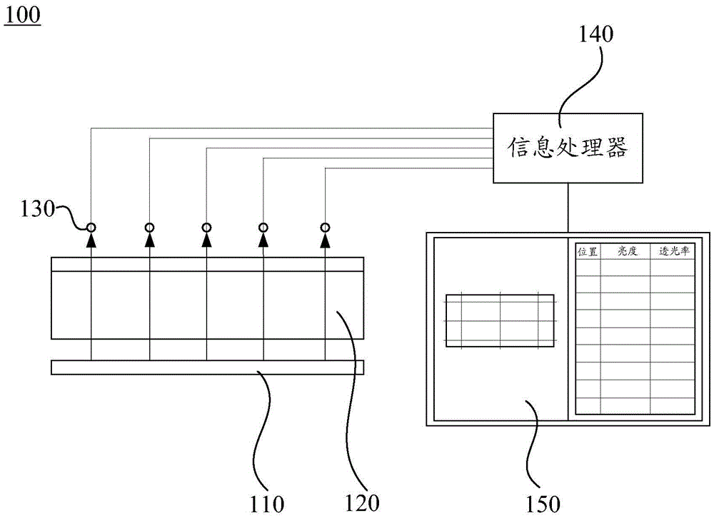
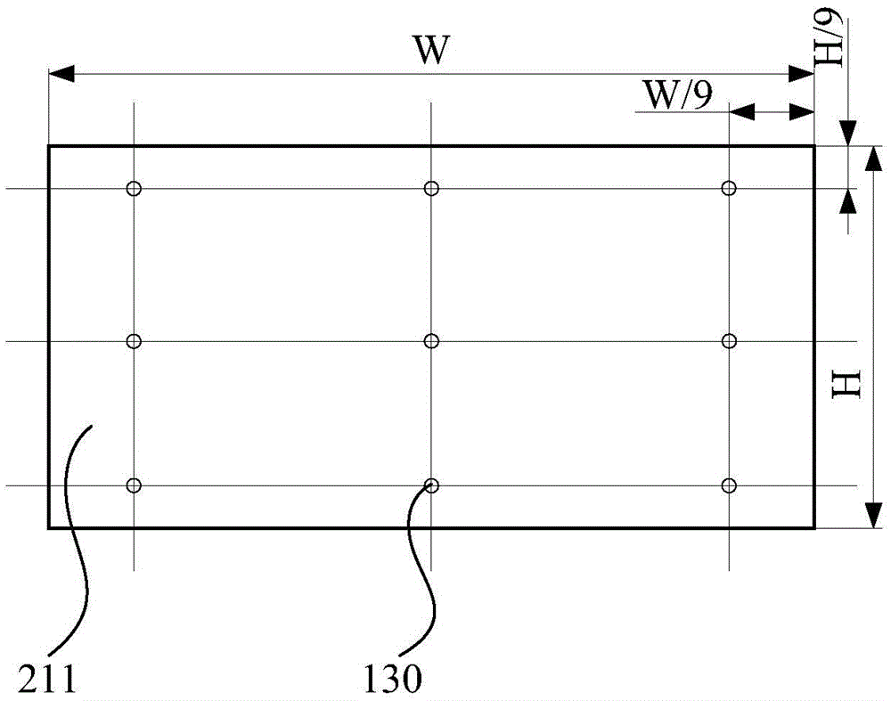
technical field [0001] The invention relates to the field of display technology, in particular to a backlight module, a light transmission uniformity detection system and an LED mixing and matching method thereof. Background technique [0002] At present, with the rapid development of technology, more and more occasions need to use large-scale LED display modules to display advertising information, commodity display information, conference information and so on. However, a common display module usually leads to a decrease in the light transmission uniformity of the screen when it is of a certain size. Moreover, for large-area splicing walls, advertising screens, etc., it needs to be formed by splicing multiple ordinary display modules, but because the splicing effect cannot achieve a perfect construction, it will make the large-area splicing walls, advertising screens, etc. emit light as a whole. The uniformity will be reduced, so the problem of uniformity of light output f...

Claims


Application Information

Patent Timeline
Patent Type & Authority Applications(China)
IPC IPC(8): G01M11/02F21S8/00F21V7/00F21Y115/10
CPCF21S8/00F21V7/00G01M11/02
Inventor 谈宝林卿恩光巫禹马骁骐陆敏康江辉
Owner 深圳英伦科技股份有限公司
Learn More