A mechanized oil pipe rowing machine for oil field

It is a technology of pipe rowing machine and oil pipe, which is applied in the direction of drill pipe, casing pipe, drill pipe, etc. It can solve the problems of hidden dangers of manual operation and high labor intensity of workers, and achieve the reduction of labor intensity, obvious use effect and stable operation and use performance. Effect

Inactive Publication Date: 2018-05-15
CHINA PETROLEUM & CHEM CORP +1
View PDF7 Cites 0 Cited by
  • Summary
  • Abstract
  • Description
  • Claims
  • Application Information

AI Technical Summary

Problems solved by technology

[0002] Oilfield tubing sending and receiving, repairing and inventory management are all provided by the second-level unit factories and stations. With the refinement of oilfield production and operation management, according to the requirements of standardized on-site placement, according to the "oil pipe layered discharge, ten out of ten According to the principle of placement, they are discharged on the pipe racks on the site respectively, and more than 12.5 million meters of oil pipe rods need to be placed every year; at present, the standardized discharge of oil pipes is completely manual operation, and each pipe rack is discharged by 4-5 people. The oil pipe is transported to the pipe rack by the pipe grasping machine, one person steps on the oil pipe and rolls with his feet to arrange them together, and then manually pushes and pulls the oil pipe couplings to line up. This discharge method is very labor-intensive for workers. Moreover, there are certain safety hazards in manual operation.

Method used


Image

  • A mechanized oil pipe rowing machine for oil field
  • A mechanized oil pipe rowing machine for oil field
  • A mechanized oil pipe rowing machine for oil field

Examples


Embodiment Construction

[0026] The detailed description and technical content of the present invention are described below with the accompanying drawings, but the accompanying drawings are only provided for reference and description, and are not intended to limit the present invention.

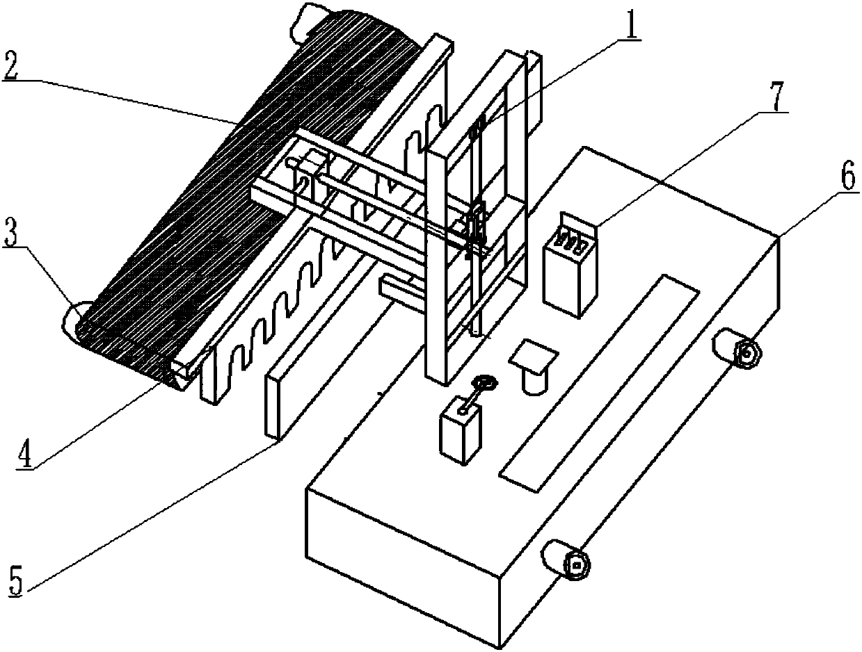
[0027] Refer to attached figure 1 , a mechanized tubing rowing machine for an oil field, comprising a tube lifting mechanism 1, a tube telescoping mechanism 2, a tube pulling mechanism 3, a tube scraper mechanism 4, a tube baffle mechanism 5, an electric traveling mechanism 6, Electric control operating mechanism 7. The pipe lifting mechanism 1 is welded on the frame of the pipe running mechanism 6, the pipe telescopic mechanism 2 is installed on the sliding lifting plate of the pipe lifting mechanism 1, and the pipe pulling mechanism 3 is connected to the pipe scraper mechanism 4 , The pipe scraper mechanism 4 is fixedly connected to the pulley of the pipe telescopic mechanism 2, below the telescopic roller assembl...


PUM


Abstract

The invention discloses a mechanized tubing rowing machine for oil fields, which comprises a tube lifting mechanism, a tube telescoping mechanism, a tube pulling mechanism, a tube scraper mechanism, a tube baffle mechanism, an electric walking mechanism, and an electric control operation mechanism. Institutional composition. The tube lifting mechanism is designed and installed with a hydraulic cylinder to realize the lifting of the tube mechanism, which is welded on the frame of the traveling mechanism; the tube expansion mechanism is designed with rollers, slideways and turbine worms to realize telescopic expansion, and is installed on the sliding lifting plate of the tube lifting mechanism; The pipe pulling mechanism is connected to the pipe scraper mechanism with a rolling belt structure; the pipe scraper mechanism is designed to be fixedly connected to the pulley of the pipe expansion mechanism by the design of the oil pipe joint hoop; the pipe baffle mechanism is welded on the pipe lifting mechanism. The mechanism bracket is mounted on the horizontal support; the electric control operating mechanism is installed and connected to the electric traveling mechanism; the electric traveling mechanism is integrally connected with the frame and the pipe arrangement to realize the mechanized discharge of the oil pipe, improve the efficiency of the pipe arrangement, and reduce the labor intensity of the manual arrangement of the workers.

Description

technical field [0001] The invention relates to the storage and distribution management technology of oil pipes in oil fields, in particular to a mechanized oil pipe rowing machine for oil fields. Background technique [0002] Oilfield tubing sending and receiving, repairing and inventory management are all provided by the second-level unit factories and stations. With the refinement of oilfield production and operation management, according to the requirements of standardized on-site placement, according to the "oil pipe layered discharge, ten out of ten According to the placement principle, they are discharged on the pipe racks on the site respectively, and more than 12.5 million meters of oil pipe rods need to be placed every year; at present, the standardized discharge of oil pipes is completely manual operation, and each pipe rack is discharged by 4-5 people. The oil pipe is transported to the pipe rack by the pipe grasping machine, one person steps on the oil pipe and ...

Claims


Application Information

Patent Timeline
Patent Type & Authority Patents(China)
IPC IPC(8): E21B19/14
Inventor 郑雪梅程爱国綦耀升吴俊徐福刚何张华刘建生赵法武
Owner CHINA PETROLEUM & CHEM CORP
Why Eureka
Try Eureka