Tread comprising a directional tread pattern

A tread and pattern block technology, which is applied in the direction of tire tread/tread pattern, transportation and packaging, tire parts, etc., can solve problems such as hindering water flow, and achieve the effect of improving lateral grip and increasing slenderness

Active Publication Date: 2016-05-25
OCIETE DE TECH MICHELIN
View PDF6 Cites 1 Cited by
  • Summary
  • Abstract
  • Description
  • Claims
  • Application Information

AI Technical Summary

Problems solved by technology

Firstly, the presence of the central main block impedes the flow of water and makes its removal through the curved grooves suboptimal

Method used


Image

  • Tread comprising a directional tread pattern
  • Tread comprising a directional tread pattern
  • Tread comprising a directional tread pattern

Examples


Embodiment Construction

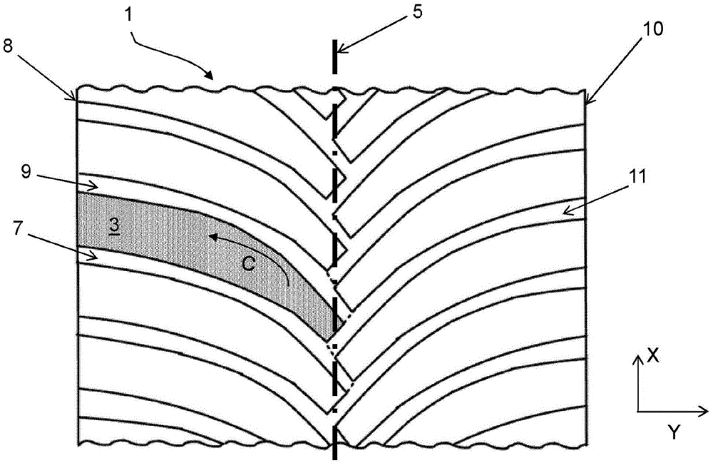
[0036] figure 1 A partial view of a tread 1 according to a first embodiment of the invention is schematically depicted.

[0037] The tread 1 comprises a plurality of rubber blocks 3, one of which has here been painted gray to make the invention easier to understand. Said blocks are formed on each side of a median plane 5 which divides the tread 1 into two parts. Here, each block 3 extends continuously towards the outside of the tread at the median plane 5 , ie said block is not divided in the direction of the outside of the tread by circumferential grooves and / or offset grooves. More particularly, each block is delimited by a first groove 7 , a second groove 9 and a third groove 11 . A first groove 7 extends at the median plane 5 towards the first edge 8 of the tread and a second groove 9 also extends at the median plane 5 towards this same first edge 8 but with an offset in the circumferential direction . The first groove 7 and the second groove 9 have the same curvature ...


PUM


Abstract

The invention relates to a tire tread comprising a plurality of blocks (3) made of rubber material, which are formed on both sides of a mid-plane (5) separating said tread (1) into two portions. Each block (3) continuously extends from the mid-plane to the outside of the tread. Each block is defined by two grooves (7, 9) which lead to a first edge (8) of the tread and have a curvature C, and by a third groove (11) which extends from the first groove (7), at the mid-plane (5) of the tread, to a second edge (10) of said tread that is opposite the first edge (8), the second groove (9) leading into said third groove (11).

Description

technical field [0001] The present invention relates to a motor vehicle tire tread comprising a directional tread pattern, and more particularly to a tread having a plurality of curved grooves extending on each side of a median plane. Background technique [0002] Document US4057089 discloses a motor vehicle tire tread comprising a directional tread pattern. More specifically, the tread comprises a plurality of curved grooves extending on each side of a median plane. The curved grooves respectively start at one of the edges of the tread and extend towards the median plane, but do not reach it. Thus, said tread pattern comprises a central main block extending in the circumferential direction, to which a plurality of sub-blocks defined by said curved grooves are attached. [0003] The tread disclosed in document US4057089 has a certain number of disadvantages. Firstly, the presence of the central main block hinders the flow of water and makes its removal through the curved ...

Claims


Application Information

Patent Timeline
IPC IPC(8): B60C11/03
CPCB60C11/0302B60C11/1236B60C11/1369B60C2011/0313B60C2011/0358B60C2011/0374B60C2011/1209
Inventor B·弗伦克尔N·雅莫E·佩里耶H·埃莫里纳
Owner OCIETE DE TECH MICHELIN
Why Eureka
Try Eureka