Eureka AIR delivers breakthrough ideas for toughest innovation challenges, trusted by R&D personnel around the world.

Distributed power flow controller and control method therefor

A technology of a power flow controller and control method, which is applied to AC network circuits, flicker reduction of AC networks, electrical components, etc., to achieve the effects of improving flexibility and reliability, balanced power flow distribution, and high reliability

Active Publication Date: 2016-05-25
WUHAN UNIV OF TECH
View PDF3 Cites 15 Cited by
  • Summary
  • Abstract
  • Description
  • Claims
  • Application Information

AI Technical Summary

Problems solved by technology

[0005] However, the topological structure, control method, and installation method of DPFC research carried out at present are only suitable for non-split conductors, while 1000kV, 500kV, and 220kV systems mostly use split conductors, and 500kV and above systems mostly use 4-split and 6-split conductors

Method used


Image

  • Distributed power flow controller and control method therefor
  • Distributed power flow controller and control method therefor
  • Distributed power flow controller and control method therefor

Examples


Embodiment Construction

[0031] In order to make the object, technical solution and advantages of the present invention clearer, the present invention will be further described in detail below with reference to the accompanying drawings and embodiments, taking 2 split wires as an example.

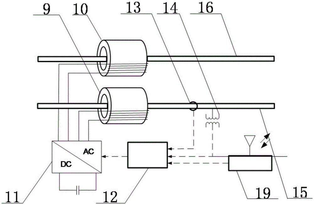
[0032] refer to Figure 1 ~ Figure 4 As shown, the distributed power flow controller of the present invention is installed on the transmission line 2, and the two ends of the transmission line are provided with a head-end Y-△ transformer 1 and an end Y-△ transformer 4. The controller includes parallel side equipment and The equipment on the series side and the equipment on the parallel side include a three-phase converter 8 and a single-phase converter 6 arranged back to back, and a DC capacitor is connected in parallel between the DC side of the three-phase converter 8 and the DC side of the single-phase converter 6 7. The AC side of the three-phase converter 8 is connected to the transmission line 2 through the △...


PUM


Abstract

A distributed power flow controller and a control method therefor are disclosed. The controller is mounted on a power transmission line, wherein the distributed power flow controller comprises shunt-wound side equipment and series-wound side equipment; each phase of power transmission line is split into multiple split conductors; the series-wound side equipment comprises multiple groups of single-phase power flow compensators connected with each phase of power transmission line in series separately; each group of certain-phase power flow compensators shares a set of converter, controller, current transformer, voltage transformer and communication module; each group of certain-phase power flow compensators also comprises multiple single-turn transformers matched with the number of the split conductors; and the alternating current side of the corresponding converter is connected to each split conductor through each single-turn transformer separately. The control method is carried out by the steps of comparing the each-phase transmission power target value with an actually collected and calculated transmission power parameter difference value; trigging control on the converter; optimizing and switching switch sequences of the converter; and realizing transmission power compensation for the power transmission line. According to the distributed power flow controller and the control method therefor, the transmission power of the power transmission system with multiple split conductors is realized; due to the control method, balanced power flow distribution is achieved; and the flexibility and reliability of equipment control are improved.

Description

technical field [0001] The invention belongs to the technical field of power system operation and control, and in particular relates to a distributed power flow controller and a control method thereof, which are suitable for multi-split conductors and are used to improve the transmission power capacity of transmission lines. Background technique [0002] At present, my country's regional power grid interconnection, UHV AC and DC, and long-distance large-capacity power transmission have basically taken shape. With the planning and construction of UHV, my country's power grid will present a complex type of power grid structure with three voltage levels of 1000, 500, and 220 kV electromagnetic ring network and AC-direct hybrid connection. The existence of the electromagnetic ring network and the natural distribution of the power flow often lead to uneven distribution of the power flow in the key transmission sections of the power grid, which limits the overall transmission capa...

Claims


Application Information

Patent Timeline
IPC IPC(8): H02J3/00
CPCH02J3/00H02J3/002
Inventor 唐爱红高梦露潘小军熊杰黄涌赵红生郑旭
Owner WUHAN UNIV OF TECH
Why Eureka
Eureka Blog
Learn More