Counter-weight-free traction type inclined elevator
An oblique elevator, no counterweight technology, applied to elevators, elevators, transportation and packaging in buildings, etc., can solve the problems of being unfavorable for saving resources and high costs, and achieve the effect of simplifying the structure and saving resources.
- Summary
- Abstract
- Description
- Claims
- Application Information
AI Technical Summary
Problems solved by technology
Method used
Image
Examples
Embodiment 1
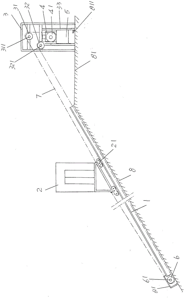
[0019] See figure 1 , shows a pair of guide rails 1, and the pair of guide rails 1 are laid along the slope 8 as the guide rail carrier in the state of keeping parallel to each other. , the elevator car 2 constitutes a rolling pair with the aforementioned pair of guide rails 1 through the guide shoe 21 at its bottom; Right end) is set on the slope top platform 81 of the slope 8, and an upper pulley 31 and a pulley 32 are rotatably arranged on the frame 3; a traction machine 4, a tensioning weight 5 and A return rope pulley 6, in the present embodiment, the aforementioned traction machine 4 is arranged on the aforementioned frame 3, and the tensioning weight 5 is directly connected to the bottom of the traction machine 4, and the aforementioned return rope pulley 6 corresponds to the aforementioned The position of the low end (the left end in the figure) of the pair of guide rails 1 is set at the bottom of the slope surface 8 . The two ends of the illustrated car traction rop...
Embodiment 2
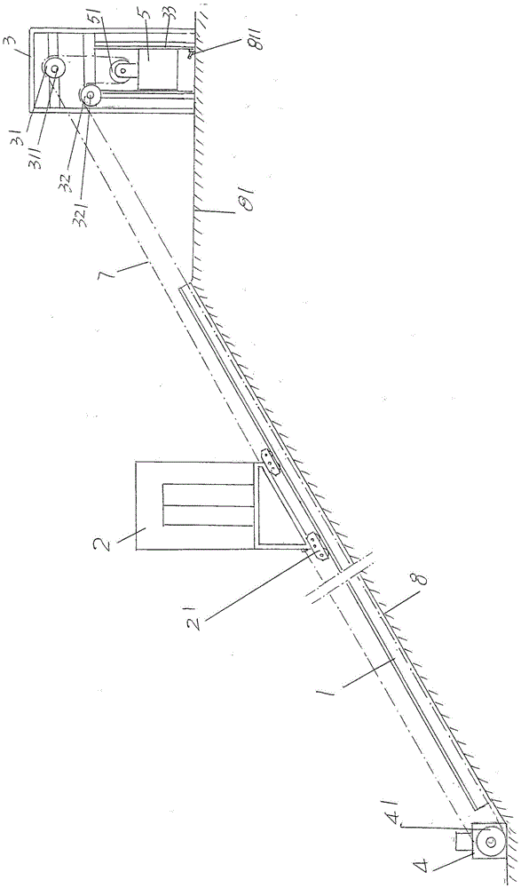
[0026] See figure 2 , in this embodiment, since the traction machine 4 is set at the bottom of the slope 8 at a position corresponding to the low end (left end) of the pair of guide rails 1, the tensioner 5 is positioned at the bottom corresponding to the frame The position below the 3 is drawn by the car traction rope 7, and the return rope pulley 6 is concurrently served by the traction sheave 41 of the traction machine 4, and a tensioning heavy sheave 51 is rotatably arranged on the top of the tensioning weight 5, The middle part of car traction rope 7 pulls up pulley 31, tension heavy rope pulley 51, lower pulley 32 and traction sheave 41 of tension weight 5 successively. All the other are the same as the description to embodiment 1.
Embodiment 3
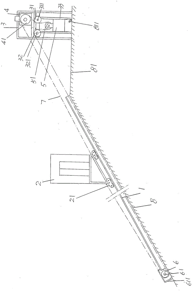
[0028] See image 3 , only the traction machine 4 is arranged on the upper part of the frame 3, and the tensioner 5 is arranged on the lower part of the frame 3 in a state separated from the traction machine 4, and the middle part of the car traction rope 7 is pulled in turn Traction pulley 41, upper pulley 31, tension heavy rope pulley 51, lower pulley 32 and return rope pulley 6 of tension heavy 5. All the other are the same as the description to embodiment 1.
PUM
 Abstract
Description
Claims
Application Information
 - R&D
- Intellectual Property
- Life Sciences
- Materials
- Tech Scout
- Unparalleled Data Quality
- Higher Quality Content
- 60% Fewer Hallucinations
Browse by: Latest US Patents, China's latest patents, Technical Efficacy Thesaurus, Application Domain, Technology Topic, Popular Technical Reports.
© 2025 PatSnap. All rights reserved.Legal|Privacy policy|Modern Slavery Act Transparency Statement|Sitemap|About US| Contact US: help@patsnap.com


