Cardiac valve support device fitted with valve leaflets

A technology of heart valves and support devices, applied in the fields of heart valves, medical science, prostheses, etc.

Inactive Publication Date: 2016-05-11
M阀门技术有限公司
View PDF9 Cites 0 Cited by
  • Summary
  • Abstract
  • Description
  • Claims
  • Application Information

AI Technical Summary

Problems solved by technology

[0005] The present invention provides an alternative solution to the problem of maintaining valve function during two-step strut / valve implantation

Method used


Image

  • Cardiac valve support device fitted with valve leaflets
  • Cardiac valve support device fitted with valve leaflets
  • Cardiac valve support device fitted with valve leaflets

Examples


Embodiment Construction

[0026] As mentioned above, the valve support device developed by the present invention provides a solution to the problem of maintaining valve function during the two-step support / valve implantation procedure and for a longer period of time (for example, on the order of weeks), in this case, the procedure The second phase (ie, implantation of the replacement valve) needs to be postponed for such a period of time.

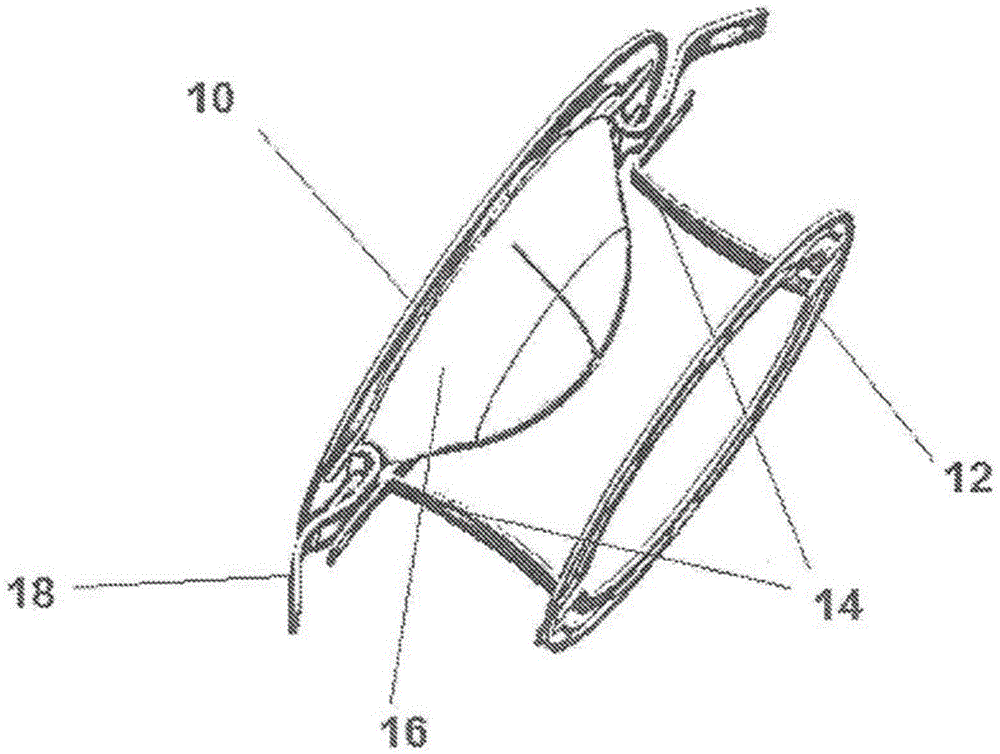
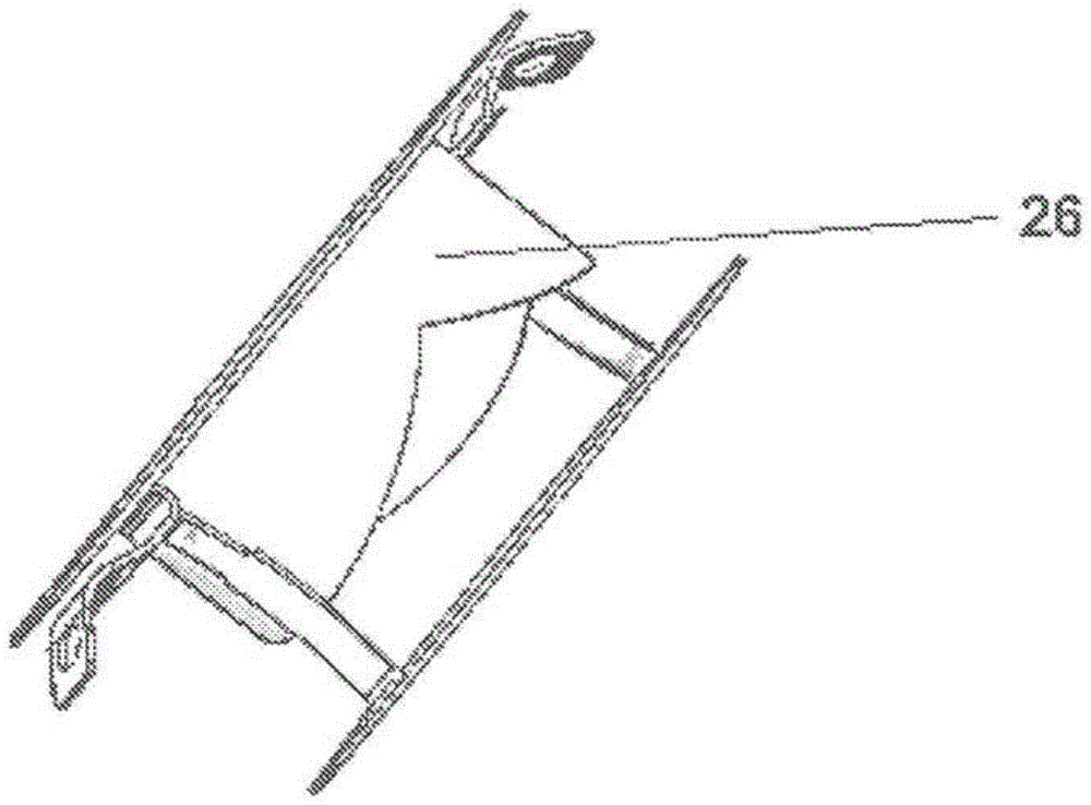
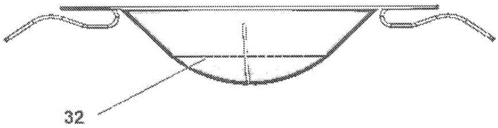
[0027] In dual ring valve support devices (as described above), one or more valve leaflets are attached to the valve support device upper ring. figure 1 An example of such a device is shown in a perspective view, the upper support element 10 and the lower support element 12 are connected to each other by two bridges 14 . The valve leaflets 16 in this figure are shown in their closed position. Also shown are two stabilizing arms 18 attached to the upper support element 10 . figure 2 The same embodiment is shown, but with the valve leaflets 26 in their open positio...


PUM


Abstract

The present invention provides a cardiac valve support device adapted for endovascular delivery to a cardiac valve, wherein said support device comprises either a single support element with valve leaflets connected thereto or two interconnected support elements having valve leaflets connected to one of said two elements. The invention further encompasses a two-stage method for implanting a replacement cardiac valve, wherein the first stage comprises delivering a valve support device fitted with one or more valve leaflets to a location near a subject's cardiac valve, such that said valve leaflets fulfill the function previously fulfilled by the native valve.

Description

technical field [0001] The present invention relates to valve support devices for use in two-stage heart valve replacement procedures. More specifically, the present invention provides valve support devices fitted with valve leaflets that can be used to maintain valve function prior to permanent replacement valve placement. Background technique [0002] A device and method for two-stage implantation for replacement of the cardiac valve membrane has been described in co-owned co-pending International Patent Application PCT / US2011 / 050232 (published as WO2012 / 031141). In the method disclosed in this document, a valve support is implanted in the region of the native valve annulus in a first stage, and subsequently, in a second stage, a replacement heart valve is implanted in the inner space of said valve support . A key feature of the valve support disclosed in this document is the presence and orientation of the two bridging elements interconnecting the upper and lower ring s...

Claims


Application Information

Patent Timeline
Patent Type & Authority Applications(China)
IPC IPC(8): A61F2/24
CPCA61F2/2418A61F2250/0059A61F2250/0063A61F2/2409A61F2/2412
Inventor M.巴克宾德S.杜比A.图比谢维茨A.格瓦
Owner M阀门技术有限公司
Why Eureka
Try Eureka