High performance wind speed detection system

A wind speed detection, high-performance technology, applied in the direction of speed/acceleration/shock measurement, measurement device, speed/acceleration/shock measurement equipment testing/calibration, etc., can solve the problem of poor flow field setting effect, narrow range range and overall performance Not advanced question

Active Publication Date: 2016-05-11
辽宁省计量科学研究院
View PDF7 Cites 4 Cited by
  • Summary
  • Abstract
  • Description
  • Claims
  • Application Information

AI Technical Summary

Problems solved by technology

Although the wind speed detection device with LDA as the standard has a small wind speed measurement uncertainty, the price of LDA is extremely expensive, the system has a long stable time, the parameter setting during detection is cumbersome, the standard centering requirements are strict, and the detection results are affected by temperature, Affected by many factors such as the quality of flue gas generation and the fixed position of the inspected instrument, the emitted flue gas is also likely to contaminate the inspected anemometer
Many wind speed detection devices of domestic metering technology institutions have simple structures, poor flow field setting effects, and simple control parts. Most of the frequency conversion speed regulation methods use backward potentiometer adjustment methods. The range is narrow, usually the uniformity of the flow field is about 1.5%, the stability of the flow field is about 0.5%, and the range ratio is less than 1:70
The stable time of the wind field is long, and the overall performance of the device is not high, which seriously restricts the development of wind speed instrument detection and scientific research work

Method used


Image

  • High performance wind speed detection system
  • High performance wind speed detection system

Examples


Embodiment Construction

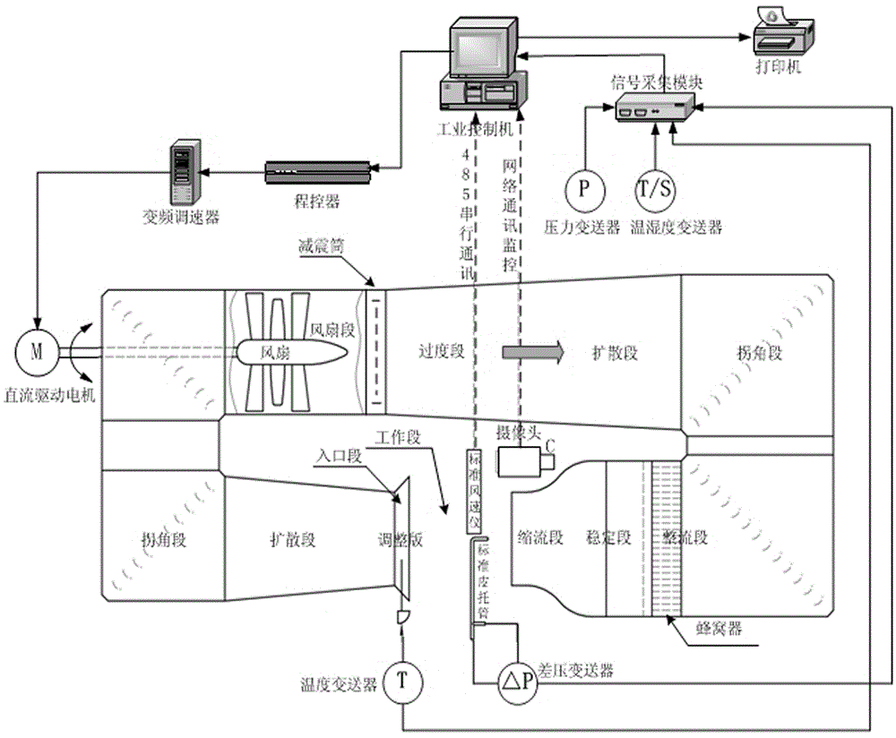
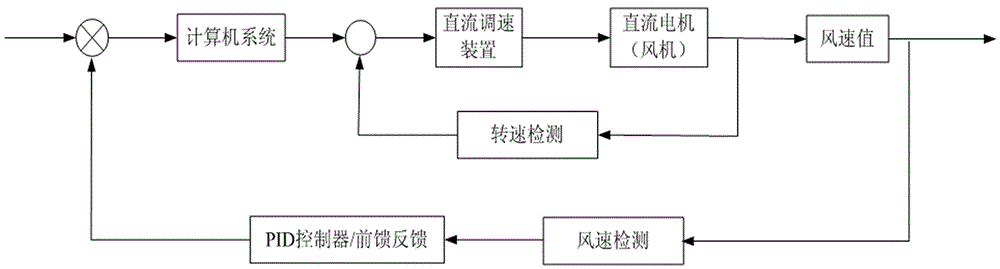
[0022] As shown in the figure, the present invention includes a DC motor, a fan, a transition section, a diffusion section, a corner section, a rectification section, a stabilization section, a constriction section, a test section, and an inlet section. The system is controlled by a combination of double closed-loop control and separate PID. The inner loop of the double closed-loop speed regulation system is the current control loop, and the outer loop is the speed control loop. The shaft section of the DC motor is equipped with a rotary encoder as the feedback of the speed control loop. . Each ring contains a regulator, which can realize the voltage regulation and magnetic speed regulation of the DC motor, which can increase the speed regulation range of the DC motor and improve the low-speed characteristics of the motor. In this control mode, the control of wind speed is realized by controlling the speed of the fan. The wind speed control system adopts a feed-forward-feedba...


PUM


Abstract

The invention discloses a high performance wind speed detection system belonging to the flow metering technology field. The flow field having advantages of wide range, high stability, and high uniformity can be generated by the system, and can be used for fast accurate detection of various wind speed measuring devices. By adopting the high performance wind speed detection system, the detection and the test of the wind speed measuring devices can be facilitated. The high performance wind speed detection system comprises an entrance segment, a first diffusion segment, a first corner segment, a fan segment, a transition segment, a second diffusion segment, a second corner segment, a rectification segment, a stabilizing segment, a flow contracting segment, and a test segment. The high performance wind speed detection system is characterized in that the entrance segment, the first diffusion segment, the first corner segment, the fan segment, the transition segment, the second diffusion segment, the second corner segment, the rectification segment, the stabilizing segment, and the flow contracting segment are sequentially connected together in an end-to-end manner to form a rectangle having an opening in a middle part of a lower long side; the opening part in the lower long side of the rectangle is the test segment, and the entrance segment and the flow contracting segment are respectively disposed on the two sides of the opening of the lower long side of the rectangle; the first corner segment and the second corner segment are respectively disposed on the short sides of the two sides of the rectangle.

Description

technical field [0001] The invention belongs to the technical field of flow measurement, and the system can generate a flow field with wide range, high stability and uniformity, and is used for fast and accurate detection of various wind speed measuring instruments. Background technique [0002] Atmospheric environment monitoring (such as the measurement of harmful smoke emissions from manufacturing enterprises), the detection of air quality in indoor ventilation environments (such as the measurement of the ventilation capacity of central air conditioners in large buildings), production safety (such as the measurement of the ventilation capacity of coal mines) Measurement), weather forecasting and other industries are widely used in a large number of air velocity measuring instruments. In addition, air flow rate is not only a measurement problem that must be solved in cutting-edge scientific research fields such as aerospace and precision measurement, but also one of the ind...

Claims


Application Information

Patent Timeline
IPC IPC(8): G01P21/02
Inventor 王振陆科王俊李宏伟刘洋韩聪李涛
Owner 辽宁省计量科学研究院
Why Eureka
Try Eureka