Three-dimensional loom weaving mechanism and using method thereof
A technology of three-dimensional looms and wefts, which is applied to looms, other opening mechanisms, textiles, etc., can solve problems such as low work efficiency and complex structures, and achieve the effects of high work efficiency, small number of structures, and strong functions
- Summary
- Abstract
- Description
- Claims
- Application Information
AI Technical Summary
Problems solved by technology
Method used
Image
Examples
Embodiment 1
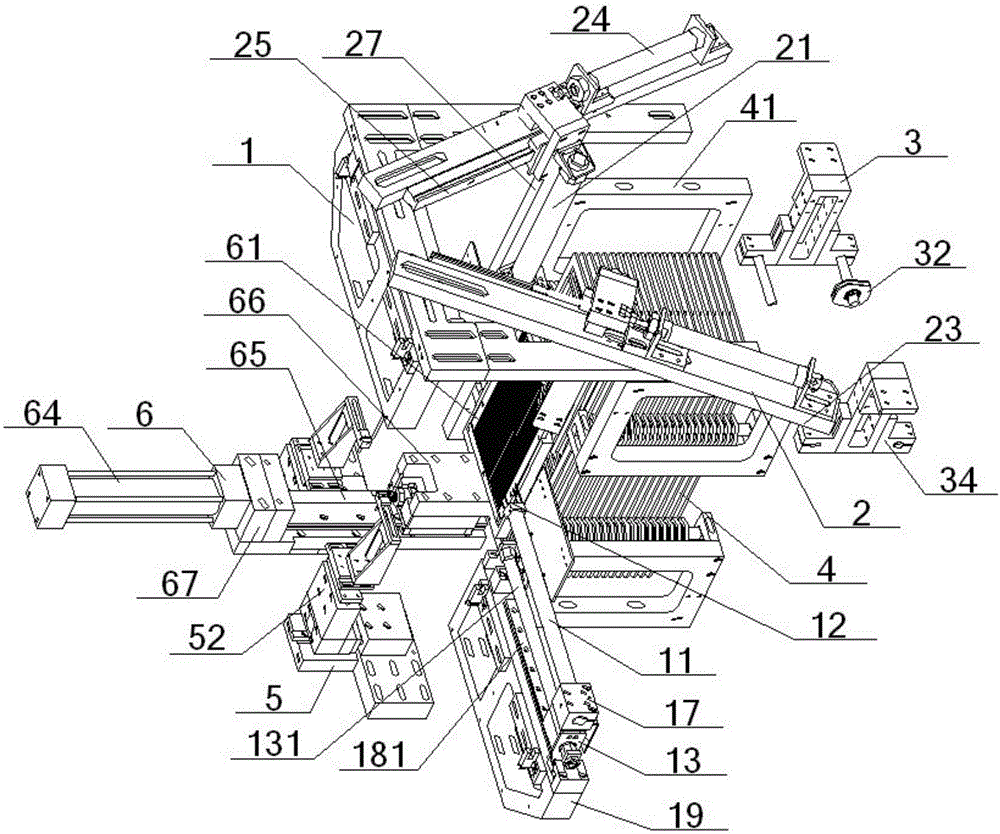
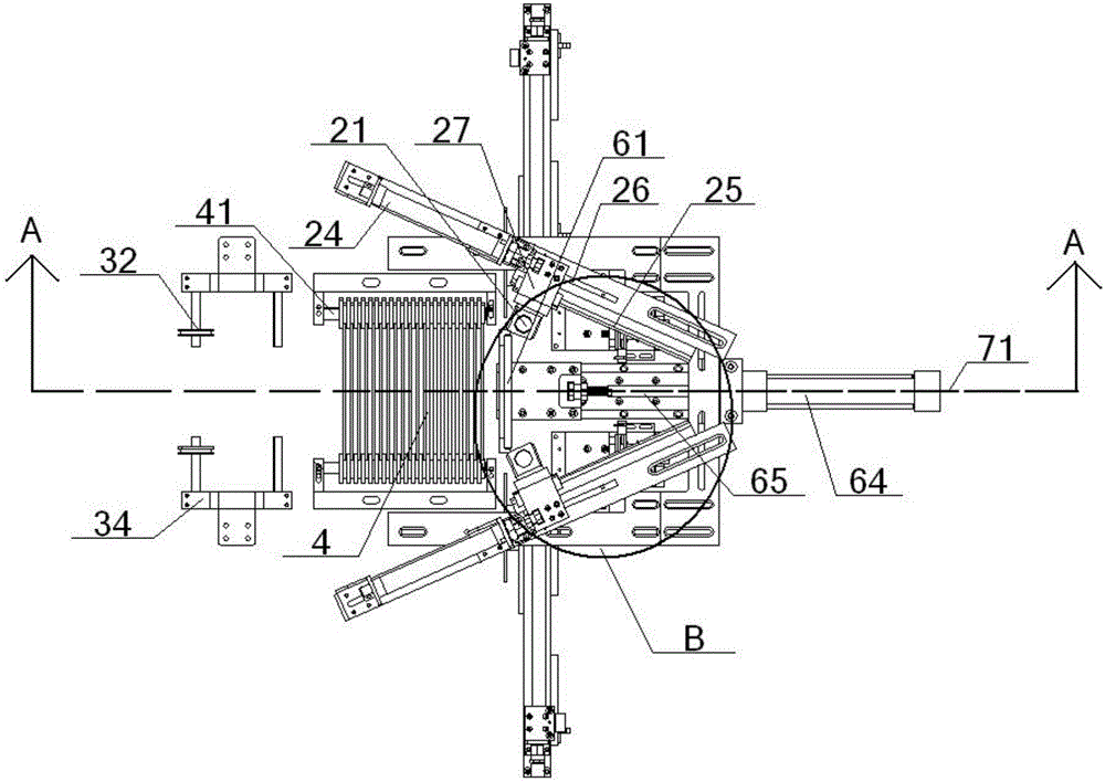
[0071] see figure 1 – Figure 15 , a three-dimensional loom weaving mechanism, comprising a weft insertion device 1, a weft thread sliding device 2, a weft thread fixing device 5, a weft beating device 6 and a shed opening device, and the weft beating device 6 is located between the heald shedding device and the weft insertion device 1 Between the stroke lines, the stroke line of the weft insertion device 1 is located between the weft beating device 6 and the receiving port 7. The device 2 is arranged left and right symmetrically with the horizontal central axis 71 as the line of symmetry, and the two weft insertion devices 1 are arranged left and right symmetrically with the horizontal central axis 71 as the line of symmetry. The lines overlap, and the two weft thread fixing devices 5 are symmetrically arranged with the horizontal central axis 71 as the line of symmetry, and the highest heights of the weft thread sliding device 2, the heald frame 4, the weft beating frame 61...
Embodiment 2
[0078] Basic content is the same as embodiment 1, the difference is:
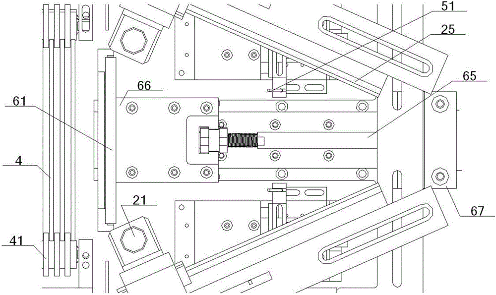
[0079] Described beating-up device 6 also comprises beating-up cylinder 64, beating-up push rod 65 and beating-up frame seat 66, and the bottom of described beating-up frame 61 is vertically connected with the top of beating-up frame seat 66, and the top of beating-up frame seat 66 The inner part is connected with an end of the beating-up push rod 65, and the other end of the beating-up push rod 65 is connected with the output end of the beating-up cylinder 64 after passing through the beating-up cylinder seat 67, and the beating-up frame seat 66, the beating-up push rod 65, the central axis of beating-up cylinder block 67, beating-up cylinder 64 all coincides with horizontal central axis 71.
Embodiment 3
[0081] Basic content is the same as embodiment 1, the difference is:
[0082] The weft thread sliding device 2 also includes a sliding base 23, a horizontal sliding cylinder 24 and a linear guide rail 25, the top of the sliding base 23 is connected with the bottom of the horizontal sliding cylinder 24, and the output end of the horizontal sliding cylinder 24 is connected to the horizontal push rod 26 The inner end of the horizontal push rod 26 is connected to the top of the vertical support 27, and the inner side of the vertical support 27 is slidably matched with the linear guide rail 25 provided on the inner side of the sliding base 23. The vertical support The outer part of 27 is connected with the inner part of vertical telescopic cylinder 21, and the output end of vertical telescopic cylinder 21 is connected with the top of the vertical push rod 22 that is positioned at directly below it, and the bottom of vertical push rod 22 is provided with The vertical slot 28 is inse...
PUM
 Abstract
Description
Claims
Application Information
 - R&D
- Intellectual Property
- Life Sciences
- Materials
- Tech Scout
- Unparalleled Data Quality
- Higher Quality Content
- 60% Fewer Hallucinations
Browse by: Latest US Patents, China's latest patents, Technical Efficacy Thesaurus, Application Domain, Technology Topic, Popular Technical Reports.
© 2025 PatSnap. All rights reserved.Legal|Privacy policy|Modern Slavery Act Transparency Statement|Sitemap|About US| Contact US: help@patsnap.com


