
Selection device for normally-used and emergency power supplies of automatic transfer switching device

A technology of automatic transfer switch and backup power supply, applied in the direction of electrical switches, circuits, electrical components, etc., can solve the problems of affecting the action of automatic transfer switches, inconvenient maintenance and maintenance, increasing production costs, etc., to achieve simple structure and improve movement reliability. The effect of stability and ease of assembly

Active Publication Date: 2016-05-04
WUXI HANKWANG ELECTRIC
View PDF4 Cites 4 Cited by
  • Summary
  • Abstract
  • Description
  • Claims
  • Application Information

AI Technical Summary

Problems solved by technology

[0004] 1. Two coils will be used in the selection device, which will inevitably increase the production cost of the product;
[0005] 2. The structure of the common and standby power selection device becomes complicated, which leads to more complicated and cumbersome assembly;
[0006] 3. The complex structure is not easy to repair and maintain;
[0007] 4. Due to the large number of parts, the friction force generated during the movement must be relatively large, which greatly affects the action of the automatic transfer switch

Method used


Image

  • Selection device for normally-used and emergency power supplies of automatic transfer switching device
  • Selection device for normally-used and emergency power supplies of automatic transfer switching device

Examples


Embodiment Construction

[0021] The present invention will be further described below in conjunction with the embodiments in the accompanying drawings:

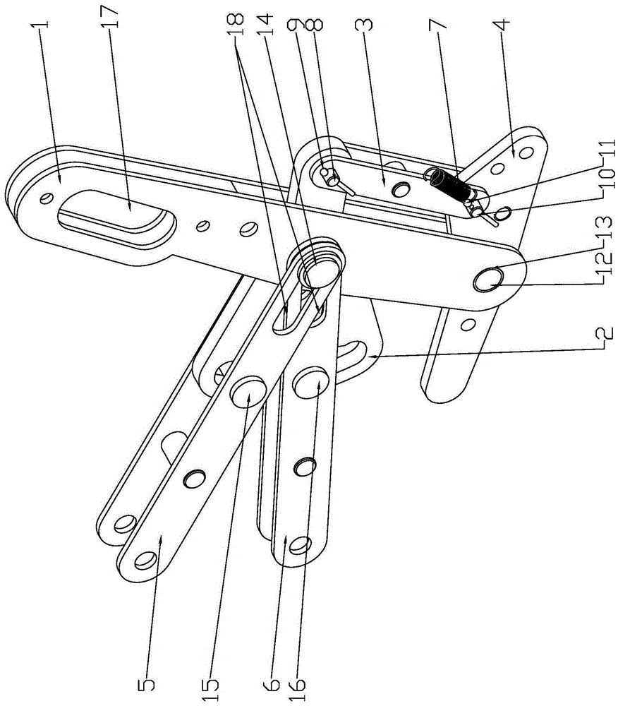
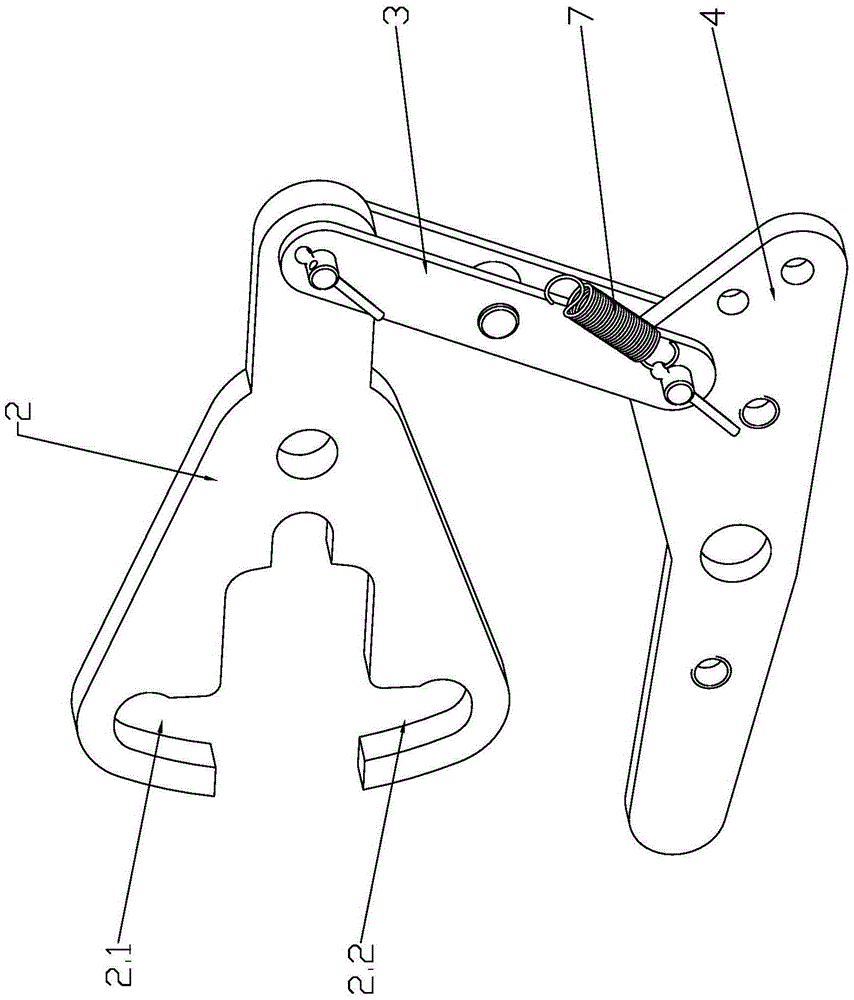
[0022] like Figure 1~2 As shown, the present invention mainly includes a control link 1 , a selection link 2 , a driven link 3 , a basic link 4 , a common power closing link 5 and a backup power closing link 6 .

[0023] The middle part of the basic connecting rod 4 is connected to the lower end of the control connecting rod 1 through a first rotating shaft 12 , and a shaft sleeve 13 is provided between the first rotating shaft 12 and the control connecting rod 1 .

[0024] The right part of the basic link 4 is connected to the lower end of the driven link 3 through the second pin shaft 10 , and the upper end of the driven link 3 is connected to the right end of the selection link 2 through the first pin shaft 8 . The second pin shaft 10 is provided with a second split pin 11 , the second pin shaft 10 is limited in position by the second split pin ...


PUM


Abstract

The invention relates to an automatic transfer switching device, in particular to a selection device for normally-used and emergency power supplies of the automatic transfer switching device, belonging to the technical field of a power supply device. The selection device comprises a control connection rod, a selection connection rod, a driven connection rod, a basic connection rod, a normally-used power supply switch-on connection rod and an emergency power supply switch-on connection rod, wherein the middle part of the basic connection rod is connected with the lower end of the control connection rod by a first rotation shaft, the right part of the basic connection rod is connected with the lower end of the driven connection rod by a second pin shaft, the upper end of the driven connection rod is connected with the right end of the selection connection rod by a first pin, and the middle part of the selection connection rod is sequentially connected with the middle part of the control connection rod and the right ends of the normally-used power supply switch-on connection rod and the emergency power supply switch-on connection rod by a central shaft. Since only a main coil is used for carrying out switch-on and switch-off motions on an automatic transfer switch, an extra latch tripping device is not needed to be arranged, thus, the production cost of a product is greatly reduced, and meanwhile, the selection device becomes more safe and reliable.

Description

technical field [0001] The invention relates to an automatic transfer switch electrical appliance, in particular to a common and backup power source selection device for automatic transfer switch electrical appliances, which belongs to the technical field of power supply equipment. Background technique [0002] The common and standby power selection device is an important component mechanism in the automatic transfer switch appliance. The existing common and standby power selection device usually consists of two coils, that is, one coil that controls the closing and opening of the common power supply, and controls the closing and opening of the standby power supply. When the coil of the common power supply is instantly energized, the pull-in of the coil drives the linkage mechanism to close the common power supply; when the coil of the standby power supply is instantly energized, the pull-in of the coil drives the The linkage mechanism is closed to the standby power supply, ...

Claims


Application Information

Patent Timeline
IPC IPC(8): H01H9/26H01H3/46
CPCH01H3/46H01H9/26
Inventor 王军管柯杨海军安建珍
Owner WUXI HANKWANG ELECTRIC
Learn More