
Automatic generation method for software graphic user man-machine interface test case

A test case, graphical user technology, applied in software testing/debugging, error detection/correction, instrumentation, etc., can solve problems such as increased training costs, knowledge loss, difficult maintenance, etc., to achieve strong ability to avoid risks and reduce personnel costs , the effect of saving maintenance costs

Active Publication Date: 2016-05-04
艾瑞克李
View PDF3 Cites 3 Cited by
  • Summary
  • Abstract
  • Description
  • Claims
  • Application Information

AI Technical Summary

Problems solved by technology

These have led to the backwardness of the current method of writing software test cases.
[0005] Looking at software development from the perspective of testing, there are two problems: First, due to the squeeze of time and tasks, it is difficult to update software requirements and design documents in a timely manner, and there is not enough motivation and resources. Testers and developers, especially personnel flow When the value is large, knowledge will be lost and training costs to deal with it will increase
Second, test cases, especially after the number reaches hundreds or thousands, are difficult to maintain when the design of the software under test changes
And because there is no structure, the quality of test cases is difficult to grasp

Method used


Image

  • Automatic generation method for software graphic user man-machine interface test case
  • Automatic generation method for software graphic user man-machine interface test case
  • Automatic generation method for software graphic user man-machine interface test case

Examples


Embodiment 1

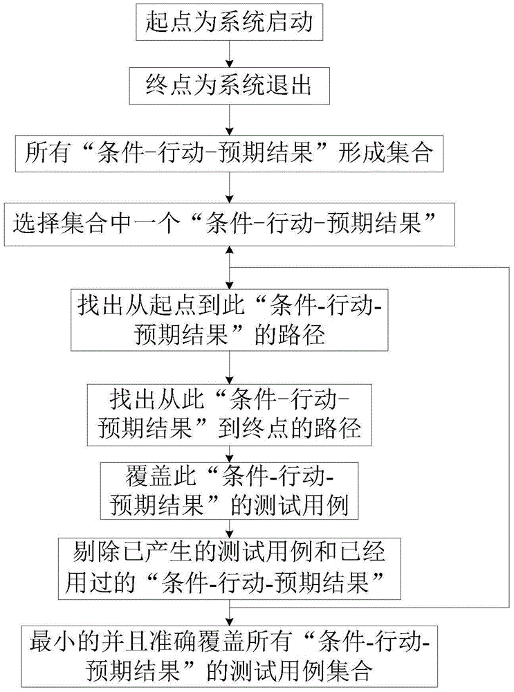
[0031] Such as figure 1 Shown, the automatic generation method of software graphical user interface test case of the present invention, comprises the steps:

[0032] Step 1: Specify the starting point of the calculated path as the system startup;

[0033] Step 2: The end point is the system exit;

[0034] Step 3: Collect the behavior specifications of the software to be tested and stipulate that all "conditions-actions-expected results" form a set;

[0035] Step 4: Select a "condition-action-expected result" in the set;

[0036] Step 5: Find out the path from the starting point to this "condition-action-expected result";

[0037] Step 6: Find out the path from this "condition-action-expected result" to the end;

[0038] Step 7: Connect the calculation results of Step 4 and Step 5 to get a test case covering this "condition-action-expected result";

[0039] Step 8: In the collection, remove the generated test cases and the used "condition-action-expected result";

[0040]...

Embodiment 2

[0043] The principle of the present invention will be explained below by taking the automatic generation of graphical user interface (GUI) test cases as an example.

[0044] The essence of the problem that the existing technicians are troubled by is: either focus on pure theoretical discussion, which is extremely complicated; or write the test case steps one by one in Microsoft Word or similar tools, and forget to examine the middle ground between the two.

[0045] In fact, it is possible to add an object-oriented structure to the software behavior specification while using ordinary language to describe the test steps. This structure is universal, and this structure can be used to realize the automatic generation of test cases with the help of the computing power of the software.

[0046] Graphical user interface (GUI) is composed of a series of controls, including edit boxes, windows, buttons and so on. In programming, many concepts need to be used according to object orient...

Embodiment 3

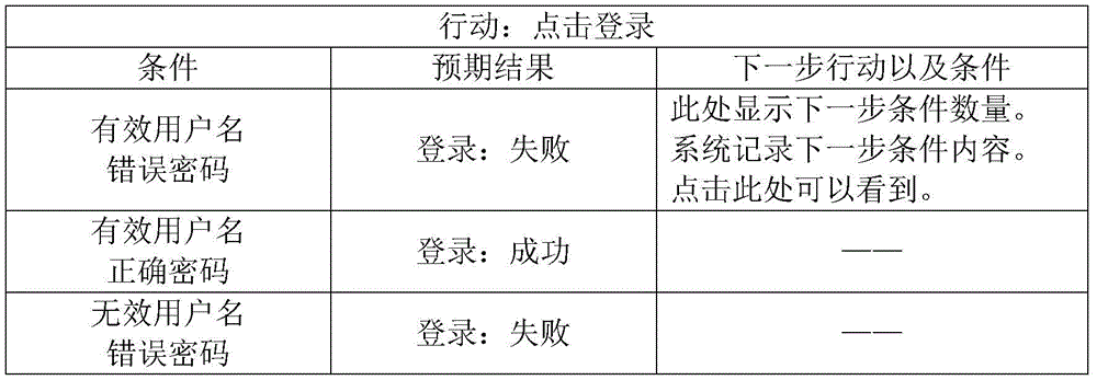
[0059] Such as figure 2 As shown, the "condition-action-expected result" state change diagram of the present invention, actual and Baidu Figure 1 In this way, each "condition-action-expected result" can be regarded as a city name, and the connection of the next action is like the road connecting the cities in the map, with one-way lines, two-way lines, and loops. You can use various path algorithms in graph theory (such as Dijkstra path algorithm), such as Baidu Figure 1 Calculate the path. And each path is a test case built on the basis of input value equivalence classes.

[0060] for example,

[0061] The first step is to specify that the starting point of the calculated path is the system startup;

[0062] The second step, the end point is the system exit;

[0063] The third step is to specify a "condition-action-expected result";

[0064] The fourth step is to find out the path from the starting point to this "condition-action-expected result";

[0065] The fifth...


PUM


Abstract

The invention relates to an automatic generation method for a software graphic user man-machine interface test case, belongs to the technical field of software inspection and detection, and solves the problems of time, labor and money waste of an existing test case writing method. The invention proposes a concept of ''condition-action-expected result''. The method comprises the following steps: defining that defining that a starting point of a calculation path is system start and an ending point of the calculation path is system exit; collecting to-be-tested software behavior specifications and defining that all ''condition-action-expected result'' units form a set; selecting one ''condition-action-expected result'' unit in the set; finding out a path from the starting point to a current position; finding out a path from the current position to the ending point; connecting calculation results to obtain a test case covering the ''condition-action-expected result'' unit; and deleting generated test cases and used ''condition-action-expected result'' units until a minimum test case set accurately covering all the ''condition-action-expected result'' units is obtained. The method has the advantages of low maintenance and updating costs, low personnel cost, good risk avoidance capability and the like, and can be widely applied to software inspection and detection occasions.

Description

technical field [0001] The invention relates to a method for automatically generating a test case of a software graphic user man-machine interface, and belongs to the technical field of software inspection and detection. Background technique [0002] Software testing is an essential part of software development, and the main technical content of the software testing process is to write software test cases, and then operate the tested program according to the test cases, evaluate software quality and find software defects. [0003] The current innovations in the software testing industry are mostly focused on the automation of software test cases, which means converting test cases into programs, and then letting software replace manual execution of test cases. And the test case itself, especially the test case preparation of the graphical user interface (GUI), is still written manually. For example: a user login test case: Step 1: Start the program, and the program user logi...

Claims


Application Information

Patent Timeline
IPC IPC(8): G06F11/36
CPCG06F11/3684
Inventor 艾瑞克·李
Owner 艾瑞克李
Learn More