
Obtaining Method of Liquid Transverse Jet Boundary

A technology of jet boundary and acquisition method, which is applied to measurement devices, instruments, optical devices, etc., can solve the problem of inability to obtain the boundary of liquid lateral jet, and achieve the effect of objective measurement results and clear and accurate physical meaning.

Active Publication Date: 2018-03-09
NAT UNIV OF DEFENSE TECH
View PDF4 Cites 0 Cited by
  • Summary
  • Abstract
  • Description
  • Claims
  • Application Information

AI Technical Summary

Problems solved by technology

[0004] The purpose of the present invention is to provide a method for acquiring the boundary of liquid transverse jet, which solves the technical problem that the boundary acquisition method of the prior art cannot quickly, quantitatively, and physically meaningfully acquire the boundary of liquid transverse jet in supersonic airflow

Method used

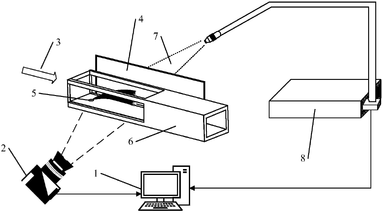

Image

  • Obtaining Method of Liquid Transverse Jet Boundary
  • Obtaining Method of Liquid Transverse Jet Boundary
  • Obtaining Method of Liquid Transverse Jet Boundary

Examples


Embodiment Construction

[0039] The accompanying drawings constituting a part of this application are used to provide further understanding of the present invention, and the schematic embodiments and descriptions of the present invention are used to explain the present invention, and do not constitute an improper limitation of the present invention.

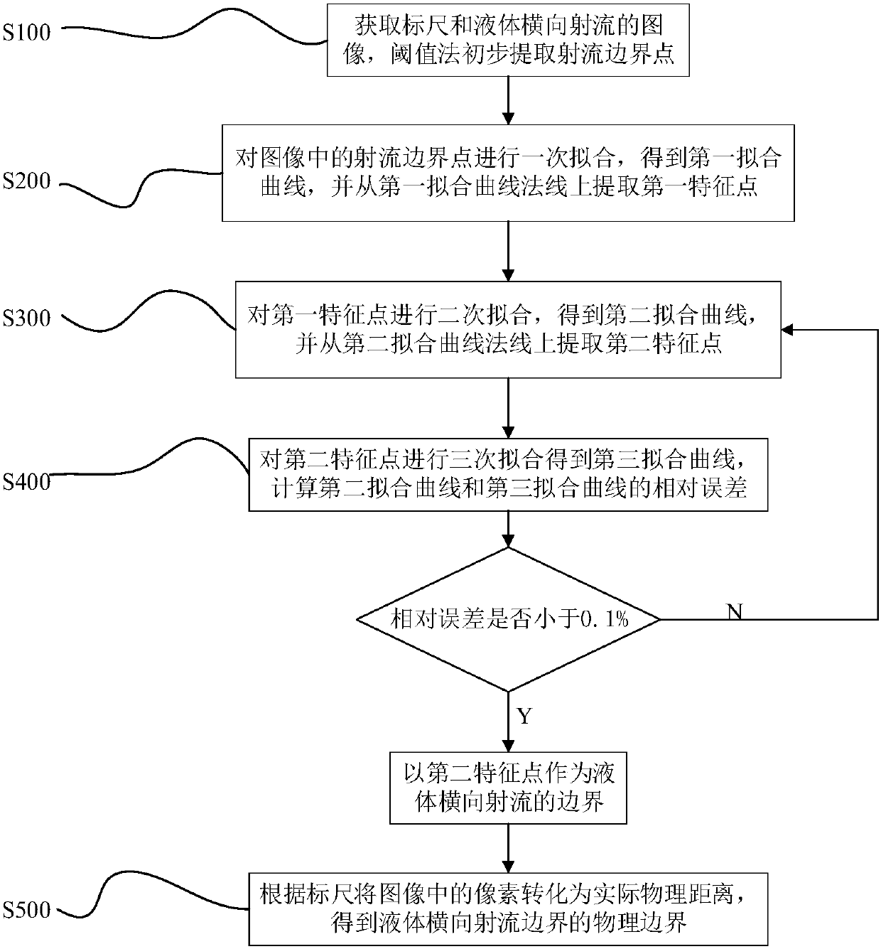
[0040] see figure 1 , the method for obtaining the liquid transverse jet boundary provided by the present invention comprises the following steps:

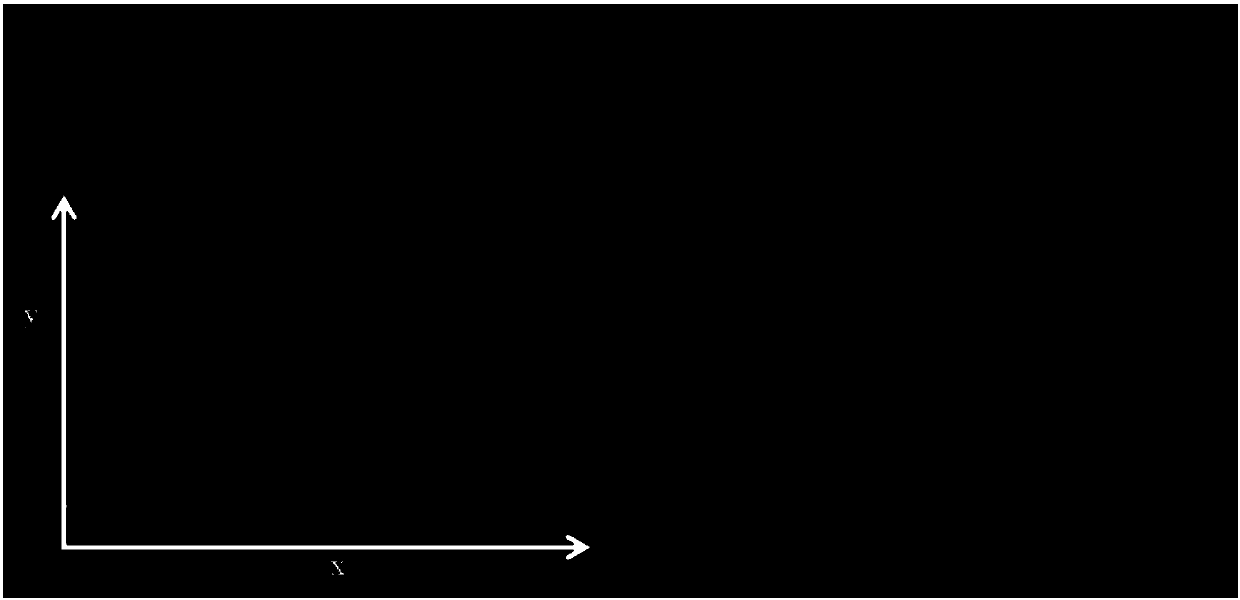
[0041] Step S100: Obtain the scale image in the jet plane by the pulse background imaging method, and then continuously shoot the liquid lateral jet in the supersonic flow field to obtain the transient image of the liquid lateral jet, pass a given gray threshold (maximum gray 10%) to get the initial jet boundary point, see image 3 ;

[0042] Step S200: Perform a fitting on the boundary points of the liquid jet in the image to obtain the first fitting curve, take the normal line along the direction of the ...


PUM


Abstract

The invention provides a method for obtaining the lateral jet boundary of liquid. Through comparing relative errors among a plurality of linear fitting curves, the method obtains a clear lateral jet boundary of liquid.

Description

technical field [0001] The invention relates to the technical field of liquid jet boundary acquisition, in particular to a liquid lateral jet boundary acquisition method. Background technique [0002] Jetting and atomization of liquid fuel is a very important process in liquid fuel engines. Among them, the boundary information of the jet has attracted much attention as an index to measure the atomization effect. It affects the degree of atomization of the lateral jet, the mixing degree of the jet and air, and also affects the spread of the jet. At present, there are two main methods to study the jet boundary: one is to obtain the macroscopic image of the transverse jet through optical imaging, and then obtain the information of the jet boundary through image processing. The other is to obtain the jet boundary through the droplet size information of a single point of optical measurement technology, and then fit the jet curve penetration depth. Commonly used optical measurem...

Claims


Application Information

Patent Timeline
Patent Type & Authority Patents(China)
IPC IPC(8): G01B11/24
CPCG01B11/24
Inventor 李晨阳吴里银李清廉
Owner NAT UNIV OF DEFENSE TECH
Learn More