A steel pipe pile device with outrigger

A technology of steel pipe piles and outriggers, which is applied to sheet pile walls, buildings, and foundation structure engineering, etc., can solve the problems of difficulty in increasing pile end resistance, difficulty in forming enlarged heads, and poor stability of pile bodies, etc., to achieve increased contact The effect of area, uniform force and large bearing capacity

Active Publication Date: 2018-01-05
STATE GRID JIANGSU ELECTRIC POWER CO LIANYUNGANG POWER SUPPLY CO +3
View PDF5 Cites 0 Cited by
  • Summary
  • Abstract
  • Description
  • Claims
  • Application Information

AI Technical Summary

Problems solved by technology

[0003] However, the existing steel pipe piles also have certain disadvantages: the pile body of the steel pipe pile is relatively smooth, so the pile side frictional resistance is relatively small; Small-diameter steel pipe piles, the pile body is too long, the slenderness ratio is too large, and the stability of the pile body is poor

Method used


Image

  • A steel pipe pile device with outrigger
  • A steel pipe pile device with outrigger
  • A steel pipe pile device with outrigger

Examples


Embodiment 1

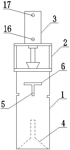
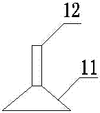
[0027] Such as figure 1 As shown, a steel pipe pile device with outriggers includes a steel pipe pile body 1, a drawing device 2, a hydraulic device 3, an extrusion cone 4 and several groups of outriggers 5; the steel pipe pile body 1 is connected to the bottom of the drawing device 2, and the top of the drawing device 2 is connected to the hydraulic device 3; the bottom of the steel pipe pile body 1 is provided with an extruding cone 4, and the extruding cone 4 is connected to the drawing device through a steel wire rope. The pulling device 2 is connected; the side wall of the steel pipe pile body 1 is provided with several groups of through holes 6, the number of the through holes 6 is the same as that of the outrigger 5, and the size of the through hole 6 is the same as that of the outrigger 5. The dimensions coincide with each other, and an outrigger 5 is arranged in the through hole 6 .

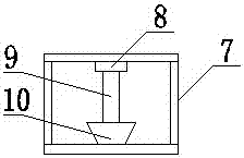
[0028] Such as figure 2 As shown, the drawing device 2 includes a fixed frame 7, ...

Embodiment 2

[0033] A steel pipe pile device with an outrigger, comprising a steel pipe pile body 1, a drawing device 2, a hydraulic device 3, an extruding cone 4 and several sets of outrigger arms 5; the top of the steel pipe pile body 1 It is connected to the bottom of the drawing device 2, and the top of the drawing device 2 is connected to the hydraulic device 3; the bottom of the steel pipe pile body 1 is provided with an extruding cone 4, and the extruding cone 4 is connected to the drawing device 2 through a steel wire rope. connected; the side wall of the steel pipe pile body 1 is provided with several groups of through holes 6, the number of the through holes 6 is the same as that of the outrigger 5, and the size of the through holes 6 is the same as that of the outrigger 5 Matching, the outrigger 5 is arranged in the through hole 6 .

[0034] The drawing device 2 includes a fixed frame 7, an adapter 8, a dowel bar 9 and a wire rope clamp 10, the bottom of the fixed frame 7 is fix...


PUM


Abstract

The invention discloses a steel pipe pile device with overhanging arms. The steel pipe pile device comprises a steel pipe pile body, a drawing device, a hydraulic device, an extrusion cone and a plurality of sets of overhanging arms. The top of the steel pipe pile body is connected with the bottom of the drawing device, and the top of the drawing device is connected with the hydraulic device; the extrusion cone is arranged at the bottom of the steel pipe pile body, and is connected with the pulling device through a steel wire rope; a plurality of sets of through holes are formed in the side wall of the steel pipe pile body, the number of the through hole is equal to that of the overhanging arms, and the size of the through holes is matched with that of the overhanging arms; and the overhanging arms are arranged in the through holes. The extrusion cone is lifted by the hydraulic device in the steel pipe pile device with the overhanging arms through the drawing device, and therefore the overhanging arms extend towards the exterior of a pile, the contact area between the overhanging arms and the soil is increased, stability of the pile body can be effectively improved, and the vertical bearing capacity of the steel pipe pile can be obviously improved.

Description

technical field [0001] The invention relates to the technical field of steel pipe piles, in particular to a steel pipe pile device with outrigger arms. Background technique [0002] Due to its material, steel pipe piles can withstand greater hammering force, and the reliability of welded joints on the construction site is greater, so they can be fully driven into deeper bearing layers. It has the advantages of strong capacity, small amount of soil displacement, easy lengthening and cutting, good quality of driven piles, and high reliability of bearing capacity. In soft soil foundations, steel pipe piles with sink openings can also reduce the extrusion of foundation soil, and have relatively little impact on adjacent buildings and underground structures, so steel pipe piles are widely used in engineering. [0003] However, the existing steel pipe piles also have certain disadvantages: the steel pipe pile body is relatively smooth, so the pile side frictional resistance is re...

Claims


Application Information

Patent Timeline
Patent Type & Authority Patents(China)
IPC IPC(8): E02D5/30E02D5/48
CPCE02D5/30E02D5/48
Inventor 张魁黄河张胜利李红董自胜王伟华蒋德稳
Owner STATE GRID JIANGSU ELECTRIC POWER CO LIANYUNGANG POWER SUPPLY CO
Why Eureka
Try Eureka