
Improved beaming device for sizing machine

A sizing machine, an improved technology, applied in the direction of transportation and packaging, conveying filamentous materials, thin material processing, etc., to achieve the effect of easy installation and reduce product quality problems

Inactive Publication Date: 2016-05-04
JIHUA 3542 TEXTILE CO LTD
View PDF14 Cites 0 Cited by
  • Summary
  • Abstract
  • Description
  • Claims
  • Application Information

AI Technical Summary

Problems solved by technology

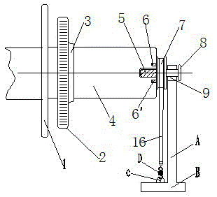
[0003] The purpose of the invention is to provide an improved sizing machine reversing device for the defects of the existing sizing machine reversing device; the improved sizing machine reversing device can effectively adjust and control the belt to sizing machine Tensile shrinkage and stretching force, its structure is reasonable, easy to install, overcome the product quality problems caused by insufficient tension

Method used


Image

  • Improved beaming device for sizing machine
  • Improved beaming device for sizing machine
  • Improved beaming device for sizing machine

Examples


Embodiment Construction

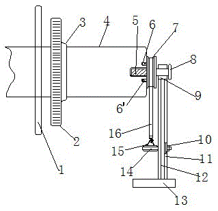
[0016] given in figure 1 , figure 2 In the existing sizing inverted shaft tension adjustment device, the lower end of the supporting column A is welded on the base B, the top of the supporting column A is provided with a semicircular groove, the bearing bush 9 is installed in the semicircular groove, and the left and right sides of the weaving shaft 4 A weaving shaft disk 1 is installed and fixed on the outer circle of the right end, with a gear 2, the center of the two ends of the weaving shaft 4 is provided with a hole, and a shaft head 5 is installed and fixed in the central holes at the left and right ends of the weaving shaft 4, and The snap ring 3 installs and fixes the gear 2 on the weaving shaft 4 on the right side of the weaving shaft disk 1; the two sides of the center hole at the right end are respectively provided with a first pin hole and a second pin hole, and the pulleys 7 are respectively set and fixed on the On the left and right ends of the weaving shaft 4,...


PUM


Abstract

The invention discloses an improved beaming device for a sizing machine. The improved beaming device is characterized in that warp beam discs are fixedly installed on the outer circle of each of the left end and the right end of a warp beam; a gear is installed and fixed to the part, on the right side of the warp beam discs, on the warp beam through a clamping ring; the part, between the warp beam discs at the left end and the right end, of the warp beam is used for winding yarn on which sizing is conducted; a hole is formed in the center of each of the left end and the right end of the warp beam; spindle heads are installed and fixed in the center holes in the left end and the right end of the warp beam; a first pin shaft on the left side face of a belt wheel is inserted in a first pin shaft hole and a second pin shaft on the left side face of the belt wheel is inserted in a second pin shaft hole; the spindle heads at the left end and the right end of the warp beam are located in a bearing bush at the upper end of a supporting pillar; the lower end of the supporting pillar is welded to a base; adjusting plates are welded to the two sides of the supporting pillar; adjusting screw rods are installed in long slotted holes through nuts; and hooks at the two ends of a belt arranged on the belt wheel in a sleeving manner are hung on hanging rings on the adjusting screw rods. The improved type sizing beaming tension adjusting device is formed.

Description

technical field [0001] The invention relates to a sizing machine component, in particular to an improved sizing machine reversing shaft device. Background technique [0002] In the existing sizing machine, due to quality problems or replacement of the sizing machine shaft, the yarn on the existing sizing weaving beam needs to be transferred to another sizing weaving beam. This process is called sizing reversing. axis. However, in the existing sizing and reversing technology, a tension spring device is used to solve the problem of tension adjustment during sizing reversing. The inverted shaft sleeve is located on the inverted shaft bracket deck, the tension belt is placed in the belt slot of the inverted shaft sleeve, and the tension belt is hooked to the tension hook by the tension springs on the left and right sides. When the weaving beam is running, because the downward pressure on the weaving beam given by the tension spring is too small, when the weaving beam is adjust...

Claims


Application Information

Patent Timeline
IPC IPC(8): B65H59/04
CPCB65H59/04
Inventor 杨杰郭双平
Owner JIHUA 3542 TEXTILE CO LTD
Learn More